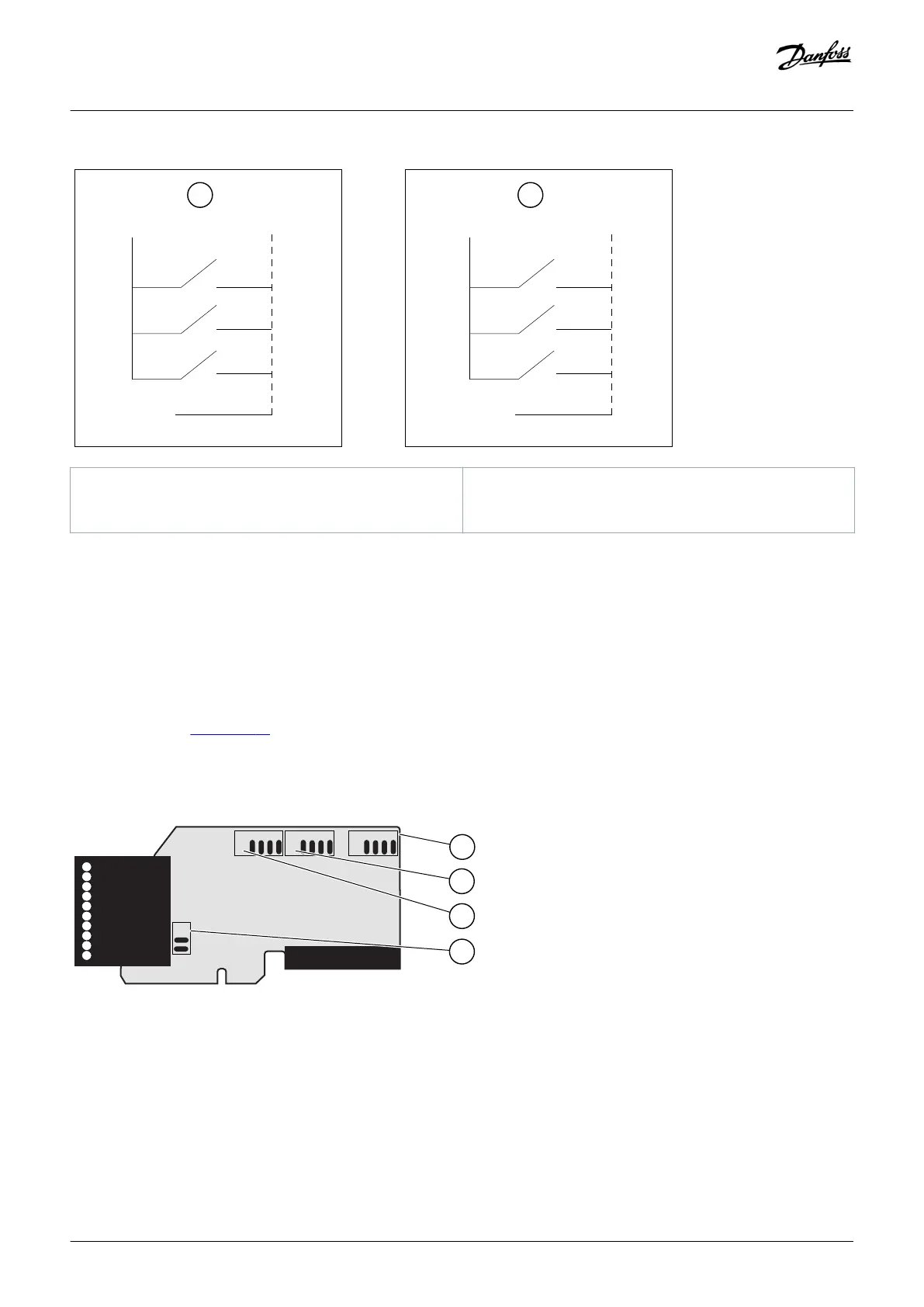
A Positive logic (+24 V is the active signal) = the input is active
when the switch is closed.
B Negative logic (0 V is the active signal) = the input is active
when the switch is closed. Set the jumper X3 to the position
'CMA/CMB isolated from ground'.
Illustration 33: Positive/Negative Logic
7.3.2.2 Jumper Selections on the OPTA1 Basic Board
The functions of the AC drive can be changed to make them better agree with local requirements. To do this, change some positions
for the jumpers on the OPTA1 board. The positions of the jumpers set the signal type of analog and digital inputs. Changing the AI/AO
signal contents requires also a change in the related board parameter in menu M7.
On the A1 basic board, there are 4 jumper blocks: X1, X2, X3, and X6. Each jumper block contains 8 pins and 2 jumpers. See the possible
jumper selections in illustration 34.
Illustration 34: Jumper Blocks on OPTA1
Control Unit
Operating guide | VACON® NXS/NXP Air-cooled
DPD00910G
80 | Danfoss A/S © 2018.06

 Loading...


