11.2.7.3 Control Structure in Flux with Motor Feedback
130BA054.11
P 3-** P 7-0*P 7-2*
+
_
+
_
P 7-20 Process feedback
1 source
P 7-22 Process feedback
2 source
P 4-11 Motor speed
low limit (RPM)
P 4-12 Motor speed
low limit (Hz)
P 4-13 Motor speed
high limit (RPM)
P 4-14 Motor speed
high limit (Hz)
High
Low
Ref.
Process
PID
Speed
PID
Ramp
P 7-00
PID source
Motor
controller
-f max.
+f max.
P 4-19
Max. output
freq.
P 1-00
Cong. mode
P 1-00
Cong. mode
Torque
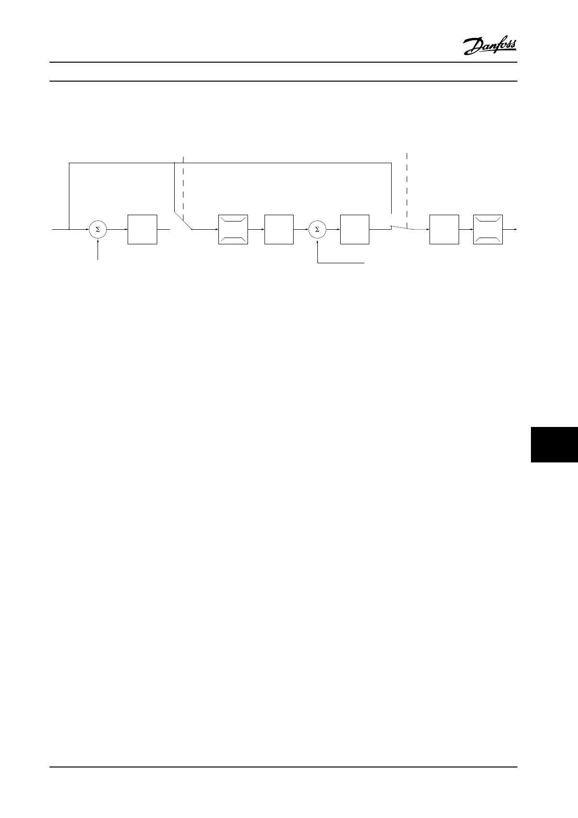
Figure 11.10 Control Structure in Flux with Motor Feedback Conguration
In Figure 11.10, the motor control in this conguration relies on a feedback signal from an encoder or resolver mounted
directly on the motor (set in parameter 1-02 Flux Motor Feedback Source). The resulting reference can be used as input for
the speed PID control, or directly as a torque reference.
Parameter 1-01 Motor Control Principle is set to [3] Flux w motor feedb and parameter 1-00 Conguration Mode is set to [1]
Speed closed loop. The speed PID control parameters are in parameter group 7-0* Speed PID Control.
Torque control can only be selected in the Flux with motor feedback (parameter 1-01 Motor Control Principle) conguration.
When this mode has been selected, the reference uses the Nm unit. It requires no torque feedback, since the actual torque
is calculated based on the current measurement of the drive.
Process PID control can be used for closed-loop control of speed or pressure in the controlled application. The process PID
parameters are in parameter groups 7-2* Process Ctrl. Feedb and 7-3* Process PID Ctrl.
11.2.7.4
Internal Current Control in VVC
+
Mode
When the motor torque exceeds the torque limits set in parameter 4-16 Torque Limit Motor Mode, parameter 4-17 Torque Limit
Generator Mode, and parameter 4-18 Current Limit, the integral current limit control is activated.
When the drive is at the current limit during motor operation or regenerative operation, it tries to get below the preset
torque limits as quickly as possible without losing control of the motor.
Basic Operating Principles ... Design Guide
MG22B222 Danfoss A/S © 01/2018 All rights reserved. 197
11 11

 Loading...


