[5]
[4]
[3]
[6]
[2]
[1]
130BB667.10
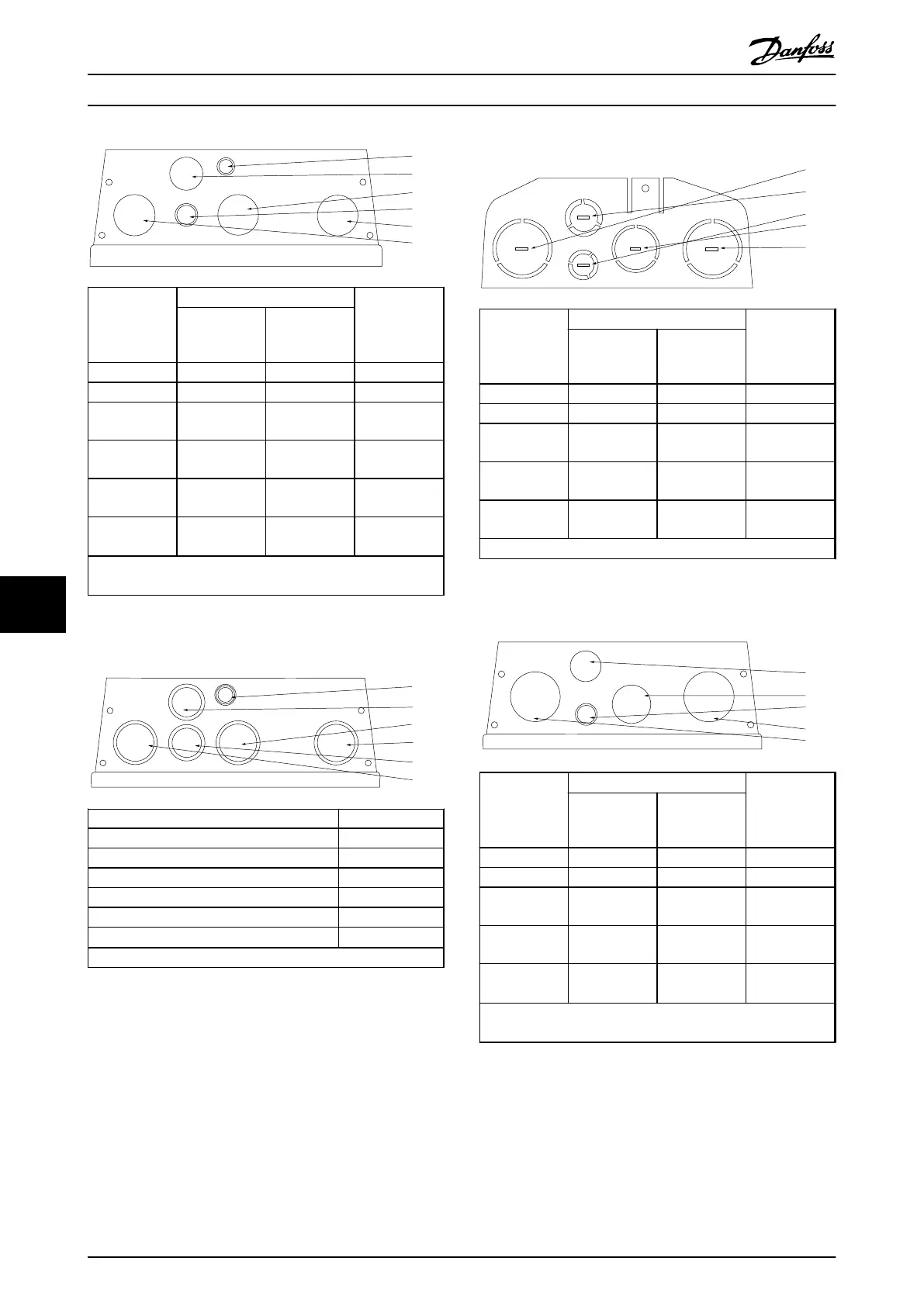
Hole number
and
recommended
use
Dimensions
1)
Nearest metric
UL [in] [mm]
1) Mains 1 34.7 M32
2) Motor 1 34.7 M32
3) Brake/load
sharing
1 34.7 M32
4) Control
cable
3/4 28.4 M25
5) Control
cable
1/2 22.5 M20
5) Control
cable
2)
1/2 22.5 M20
1) Tolerance ± 0.2 mm
2) Knock-out hole
Illustration 9.8 B1 - IP55
[6]
[5]
[3]
[2]
[4]
[1]
130BB669.10
Hole number and recommended use Nearest metric
1) Mains M32
2) Motor M32
3) Brake/load sharing M32
4) Control cable M25
5) Control cable M25
6) Control cable
22.5 mm
1)
1) Knock-out hole
Illustration 9.9 B1 - IP55 Threaded Gland Holes
[1]
[4]
[5]
[3]
[2]
130BB660.10
Hole number
and
recommended
use
Dimensions
1)
Nearest metric
UL [in] [mm]
1) Mains 1 1/4 44.2 M40
2) Motor 1 1/4 44.2 M40
3) Brake/load
sharing
1 34.7 M32
4) Control
cable
3/4 28.4 M25
5) Control
cable
1/2 22.5 M20
1) Tolerance ± 0.2 mm
Illustration 9.10 B2 - IP21
[4]
[3]
[5]
[2]
[1]
130BB668.10
Hole number
and
recommended
use
Dimensions
1)
Nearest metric
UL [in] [mm]
1) Mains 1 1/4 44.2 M40
2) Motor 1 1/4 44.2 M40
3) Brake/load
sharing
1 34.7 M32
4) Control
cable
3/4 28.4 M25
5) Control
cable
2)
1/2 22.5 M20
1) Tolerance ± 0.2 mm
2) Knock-out hole
Illustration 9.11 B2 - IP55
Electrical Installation
VLT
®
AutomationDrive FC 301/FC 302 Design Guide, 0.25-75 kW
116 MG33BF02 - Rev. 2013-12-20
99

 Loading...


