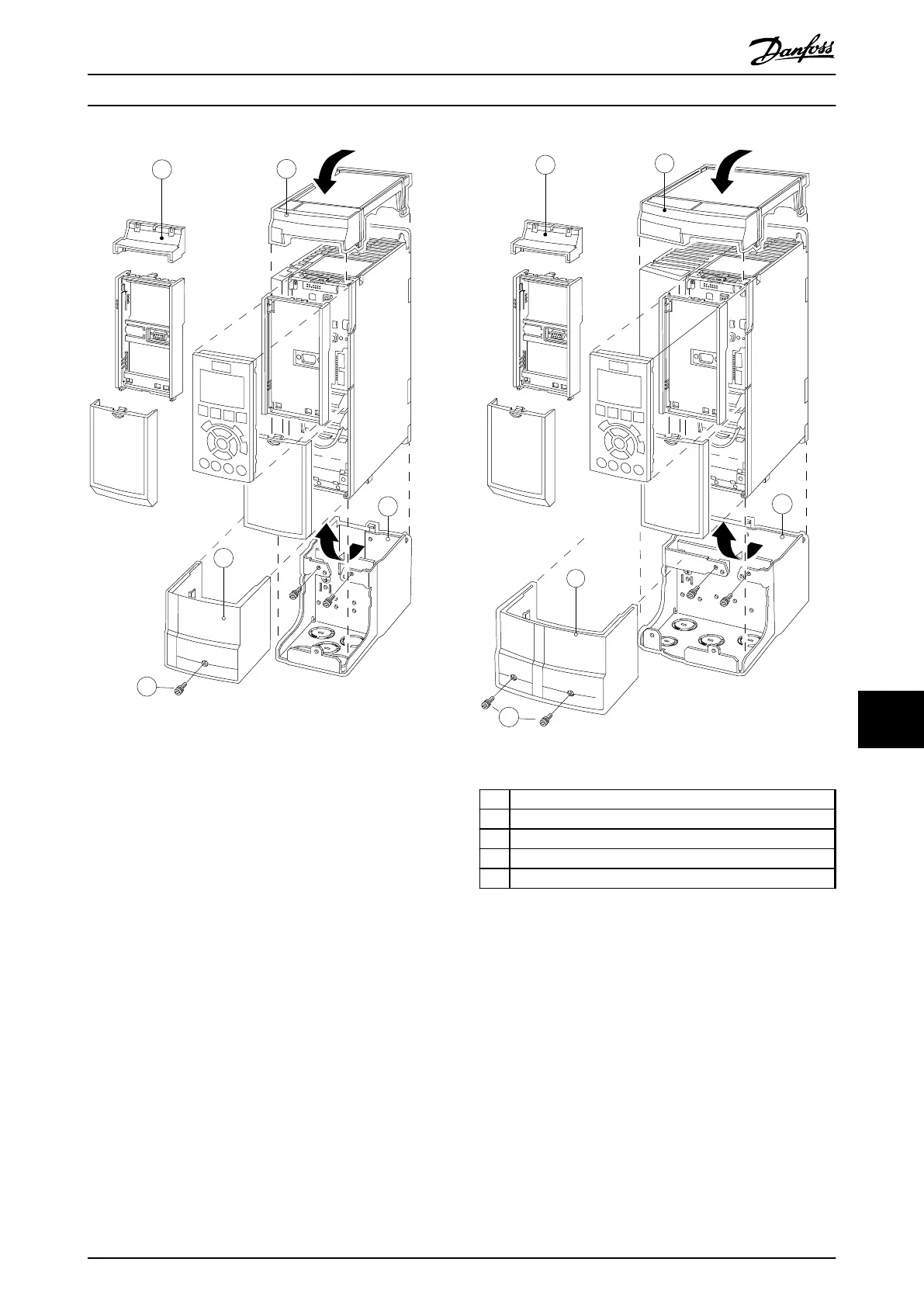
Illustration 11.23 Enclosure Type A2
Illustration 11.24 Enclosure Type A3
A
Top cover
B Brim
C Base part
D Base cover
E Screw(s)
Table 11.12 Legend to Illustration 11.23 and Illustration 11.24
Place the top cover as shown. If an A or B option is used
the brim must be fitted to cover the top inlet. Place the
base part C at the bottom of the frequency converter and
use the clamps from the accessory bag to correctly fasten
the cables
Holes for cable glands:
•
Size A2: 2x M25 and 3xM32
•
Size A3: 3xM25 and 3xM32
Options and Accessories
VLT
®
AutomationDrive FC 301/FC 302 Design Guide, 0.25-75 kW
MG33BF02 - Rev. 2013-12-20 171
11 11

 Loading...


