EasyManuals Logo

Danfoss VLT AutomationDrive Design Guide

Danfoss VLT AutomationDrive
281 pages
To Next Page IconTo Next Page
To Previous Page IconTo Previous Page
Page #119 background imageLoading...
Page #119 background image
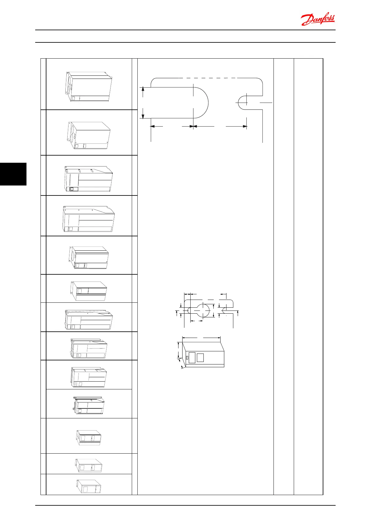
A1 A2 A3 A4 A5 B1 B2 B3 B4 C1 C2 C3 C4
130BA870.10
130BA809.10
130BA810.10
130BB458.10
130BA811.10
130BA812.10
130BA813.10
130BA826.10
130BA827.10
130BA814.10
130BA815.10
130BA828.10
130BA829.10
IP20 IP20/21 IP20/21 IP55/66 IP55/66 IP21/55/66 IP21/55/66 IP20 IP20 IP21/55/66 IP21/55/66 IP20 IP20
C
a
b
130BA648.11
f
e
B
A
a
d
e
b
c
a
e
f
130BA715.11
Accessory bags containing necessary brackets, screws and connectors are included with the drives upon delivery.
Top and bottom mounting holes (B4, C3 and C4
only)
All measurements in mm.
* A5 in IP55/66 only
Mechanical Installation - F... FC 300 Design Guide
118 MG.33.BD.02 - VLT
®
is a registered Danfoss trademark
6
6

Table of Contents

Other manuals for Danfoss VLT AutomationDrive

Questions and Answers:

Question and Answer IconNeed help?

Do you have a question about the Danfoss VLT AutomationDrive and is the answer not in the manual?

Danfoss VLT AutomationDrive Specifications

General IconGeneral
Supply Voltage3 x 200-240 V ±10% 3 x 380-500 V ±10% 3 x 525-600 V ±10%
EnclosureIP20
Output Power Range0.25 kW - 1.5 MW
Communication ProtocolsModbus RTU
Protection FeaturesOvercurrent, Overvoltage, Undervoltage, Short circuit, Ground fault, Motor overload
Ambient Temperature Range-10°C to +50°C (14°F to 122°F)

Related product manuals