7.2.9 Gland/Conduit Entry - IP21 (NEMA 1)
and IP54 (NEMA12)
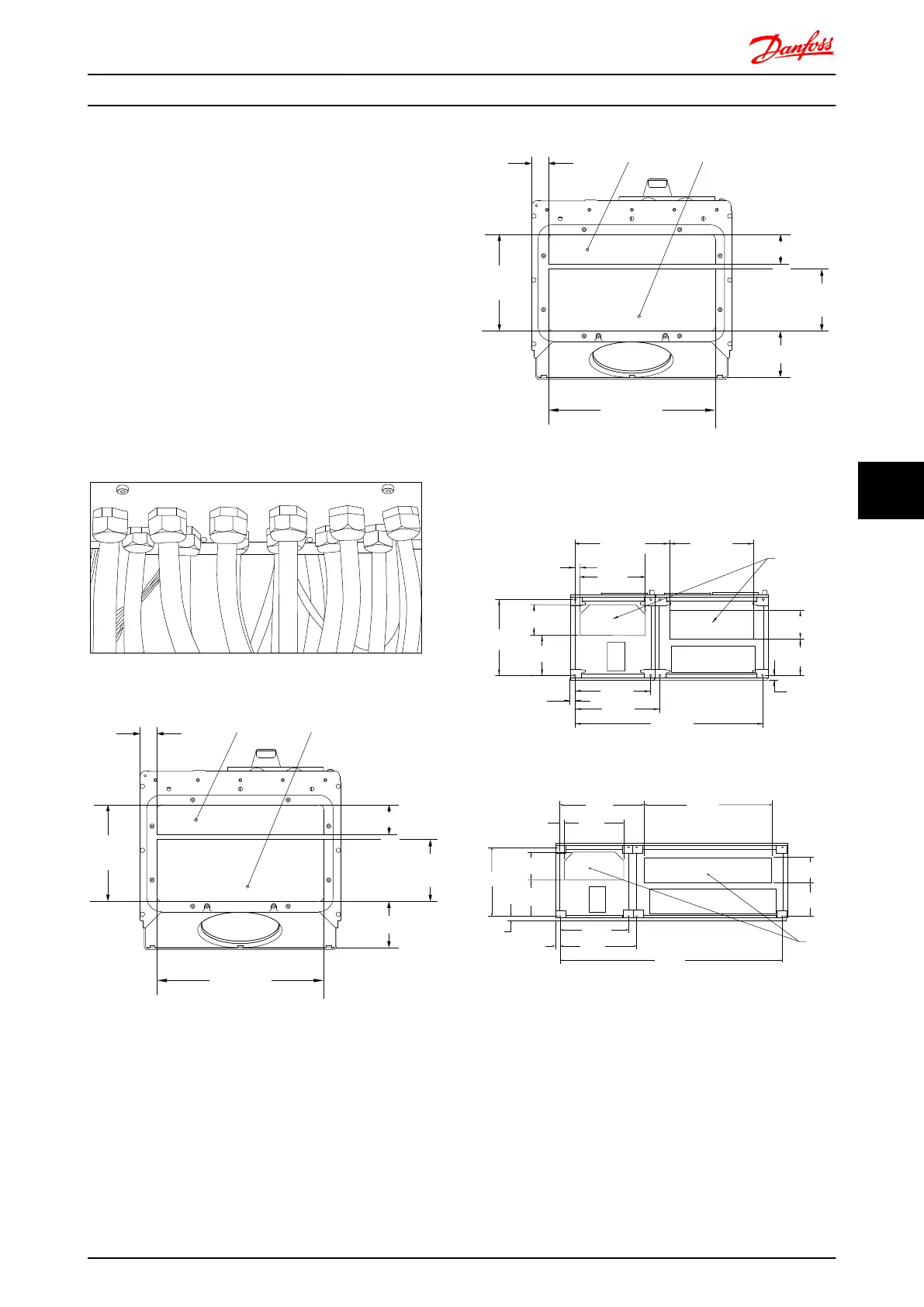
Cables are connected through the gland plate from the
bottom. Remove the plate and plan where to place the
entry for the glands or conduits. Prepare holes in the
marked area on the drawing.
NOTE
The gland plate must be fitted to the frequency converter
to ensure the specified protection degree, as well as
ensuring proper cooling of the unit. If the gland plate is
not mounted, the frequency converter may trip on Alarm
69, Pwr. Card Temp
Cable entries viewed from the bottom of the frequency
converter - 1) Mains side 2) Motor side
Illustration 7.44 Example of Proper Installation of Gland Plate.
2
1
176FA289.11
98.6
62.5
130.0
35
202.8
350
Illustration 7.45 Frame Sizes D1 + D2
2
1
176FA289.11
98.6
62.5
130.0
35
202.8
350
Illustration 7.46 Frame Size E1
F1-F4: Cable entries viewed from the bottom of the
frequency converter - 1) Place conduits in marked areas
1
130BA837.12
1328.8
(52.315)
595.8
(23.457)
533.0
(20.984)
36.2
(1.425)
281.8
(11.096)
535.0
(21.063)
216.5
(8.524)
37.7
(1.485)
460.0
(18.110)
668.3
(26.311)
593.0
(23.346)
199.5
(7.854)
258.5
(10.177)
35.5
(1.398)
Illustration 7.47 Frame Size F1
533.0
[20.984]
594.8
[23.417]
1727.8
[68.024]
35.5
[1.398]
[21.063]
258.2
[10.167]
199.5
[7.854]
37.7
[1.485]
460.0
[18.110]
655.9
[25.825]
994.3
[39.146]
216.5
[8.524]
36.2
[1.425]
281.8
[11.096]
1
130BA841.12
535.0
Illustration 7.48 Frame Size F2
Mechanical Installation - ... FC 300 Design Guide
MG.33.BD.02 - VLT
®
is a registered Danfoss trademark 153
7 7

 Loading...


