1
4
2
3
130BA012.11
61
68
69
39
42
50
53
54
55
12
13
18
19
27
29
32
33
20
37
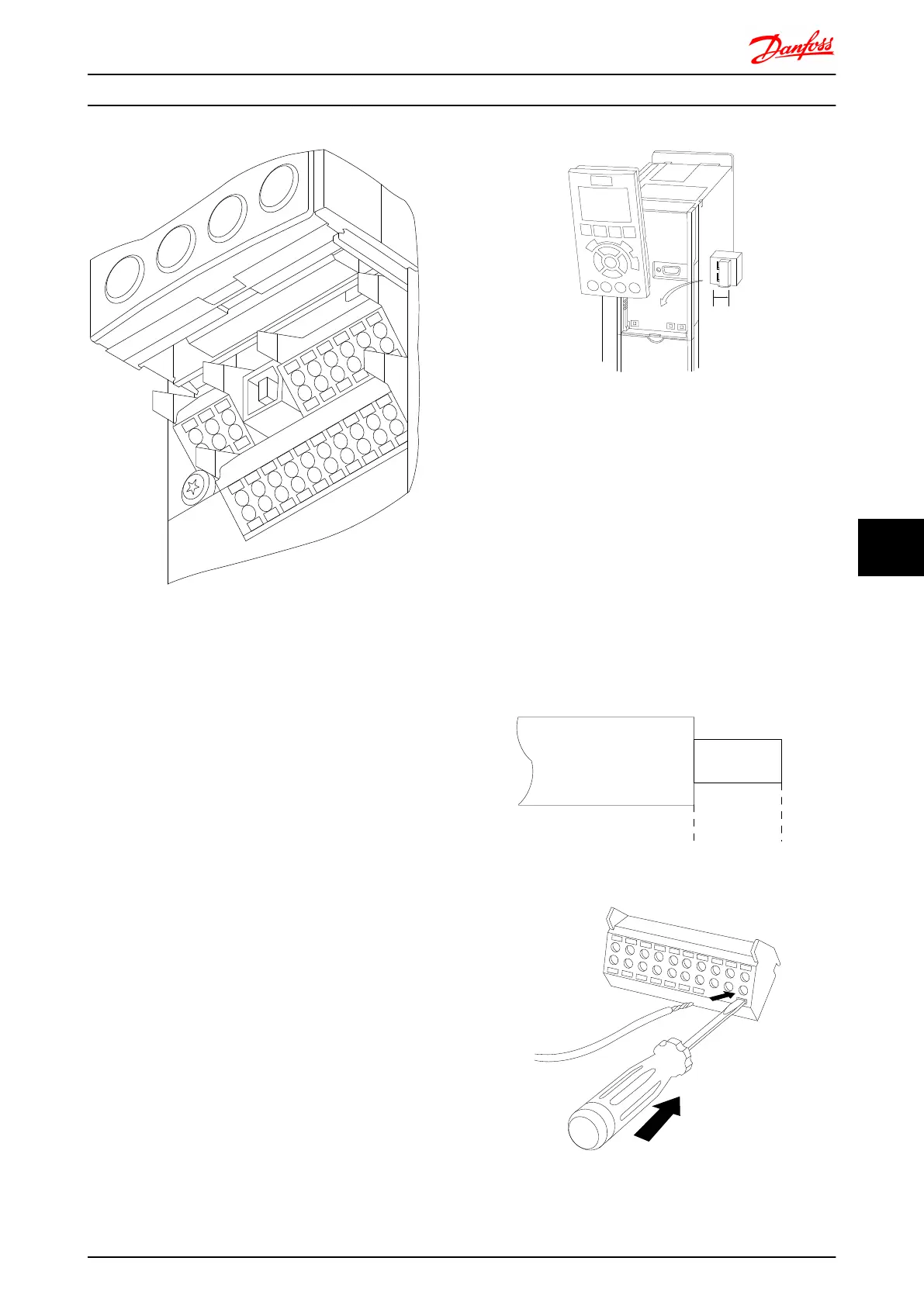
Illustration 8.56 Control terminals (all frame sizes)
8.6.4
Switches S201, S202, and S801
Switches S201 (A53) and S202 (A54) are used to select a
current (0-20mA) or a voltage (-10 to 10V) configuration of
the analog input terminals 53 and 54 respectively.
Switch S801 (BUS TER.) can be used to enable termination
on the RS-485 port (terminals 68 and 69).
See drawing Diagram showing all electrical terminals in
section Electrical Installation.
Default setting:
S201 (A53) = OFF (voltage input)
S202 (A54) = OFF (voltage input)
S801 (Bus termination) = OFF
NOTE
When changing the function of S201, S202 or S801 be
careful not to use force for the switch over. It is
recommended to remove the LCP fixture (cradle) when
operating the switches. The switches must not be operated
with power on the frequency converter.
130BT310.10
1
2
N O
V LT
BUS TER.
OFF-ON
A53 A54
U- I U- I
8.6.5 Electrical Installation, Control
Terminals
To mount the cable to the terminal:
1. Strip insulation of 9-10 mm
2.
Insert a screwdriver
1)
in the square hole.
3. Insert the cable in the adjacent circular hole.
4. Remove the screw driver. The cable is now
mounted to the terminal.
To remove the cable from the terminal:
1.
Insert a screwdriver
1)
in the square hole.
2. Pull out the cable.
1)
Max. 0.4 x 2.5 mm
130BA150.10
9 - 10 mm
(0.37 in)
Illustration 8.57 1.
Illustration 8.58 2.
Electrical Installation FC 300 Design Guide
MG.33.BD.02 - VLT
®
is a registered Danfoss trademark 211
8 8

 Loading...


