3.4 PID Control
3.4.1 Speed PID Control
1-00 Configuration Mode 1-01 Motor Control Principle
U/f
VVC
plus
Flux Sensorless Flux w/ enc. feedb
[0] Speed open loop Not Active Not Active ACTIVE N.A.
[1] Speed closed loop N.A. ACTIVE N.A. ACTIVE
[2] Torque N.A. N.A. N.A. Not Active
[3] Process Not Active ACTIVE ACTIVE
Table 3.2 Control configurations where the Speed Control is active
“N.A.” means that the specific mode is not available at all. “Not Active” means that the specific mode is available but the Speed Control is not
active in that mode.
NOTE
The Speed Control PID will work under the default parameter setting, but tuning the parameters is highly recommended to
optimize the motor control performance. The two Flux motor control principles are particularly dependant on proper tuning
to yield their full potential.
The following parameters are relevant for the Speed Control:
Parameter Description of function
7-00 Speed PID Feedback Source
Select from which input the Speed PID should get its feedback.
30-83 Speed PID Proportional Gain
The higher the value - the quicker the control. However, too high value may lead to oscillations.
7-03 Speed PID Integral Time
Eliminates steady state speed error. Lower value means quick reaction. However, too low value may lead to
oscillations.
7-04 Speed PID Differentiation Time
Provides a gain proportional to the rate of change of the feedback. A setting of zero disables the differentiator.
7-05 Speed PID Diff. Gain Limit
If there are quick changes in reference or feedback in a given application - which means that the error changes
swiftly - the differentiator may soon become too dominant. This is because it reacts to changes in the error. The
quicker the error changes, the stronger the differentiator gain is. The differentiator gain can thus be limited to allow
setting of the reasonable differentiation time for slow changes and a suitably quick gain for quick changes.
7-06 Speed PID Lowpass Filter Time
A low-pass filter that dampens oscillations on the feedback signal and improves steady state performance. However,
too large filter time will deteriorate the dynamic performance of the Speed PID control.
Practical settings of parameter 7-06 taken from the number of pulses per revolution on from encoder (PPR):
Encoder PPR
7-06 Speed PID Lowpass Filter Time
512 10 ms
1024 5 ms
2048 2 ms
4096 1 ms
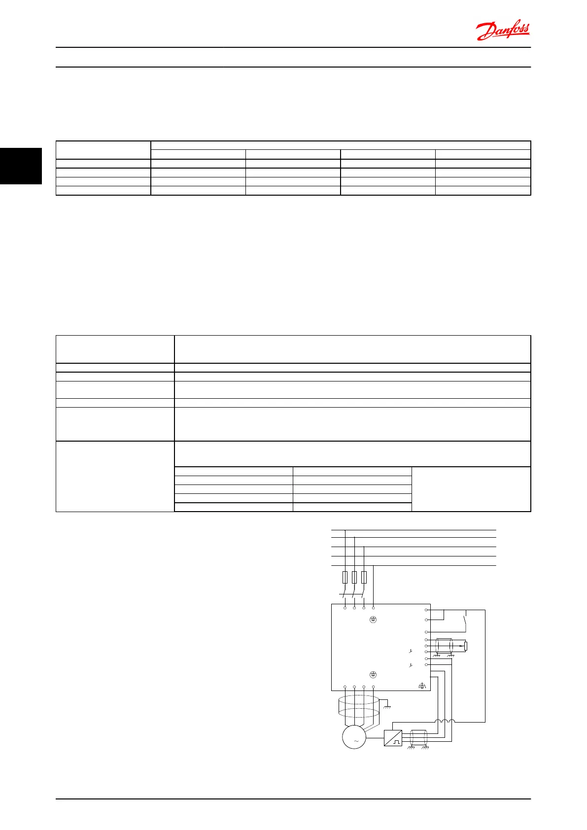
Example of how to Programme the Speed Control
In this case the Speed PID Control is used to maintain a
constant motor speed regardless of the changing load on
the motor. The required motor speed is set via a potenti-
ometer connected to terminal 53. The speed range is 0 -
1500 RPM corresponding to 0 - 10V over the
potentiometer. Starting and stopping is controlled by a
switch connected to terminal 18. The Speed PID monitors
the actual RPM of the motor by using a 24V (HTL)
incremental encoder as feedback. The feedback sensor is
an encoder (1024 pulses per revolution) connected to
terminals 32 and 33.
M
3
96 97 9998
91 92 93 95
50
12
L1 L2
L1
PEL3
W PEVU
F1
L2
L3
N
PE
18
53
37
55
20
32
33
39
24 Vdc
130BA174.10
Introduction to FC 300 FC 300 Design Guide
30 MG.33.BD.02 - VLT
®
is a registered Danfoss trademark
3
3

 Loading...


