EasyManuals Logo

Danfoss VLT AutomationDrive Design Guide

Danfoss VLT AutomationDrive
281 pages
To Next Page IconTo Next Page
To Previous Page IconTo Previous Page
Page #136 background image
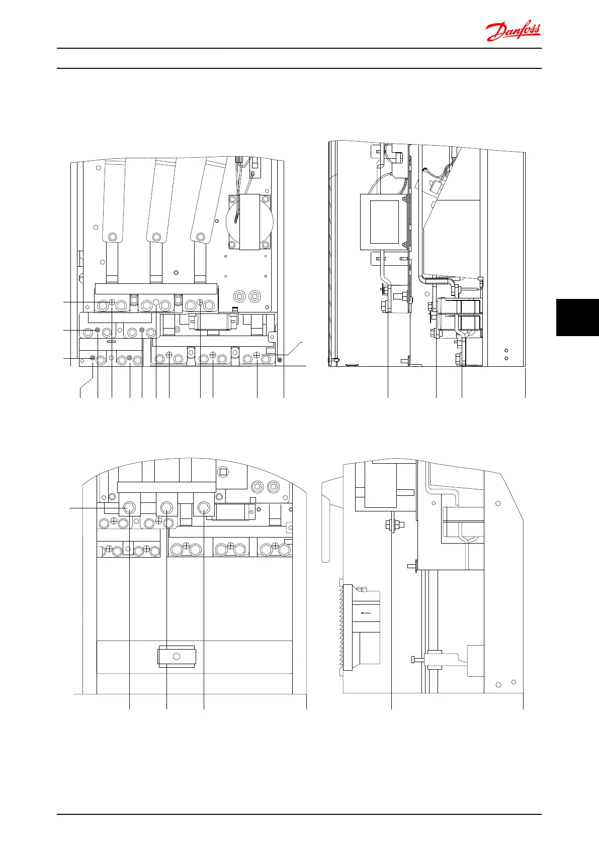
7.2.3 Terminal Locations - Frame size D
Take the following position of the terminals into consideration when you design for cables access.
0,
(0,)
0,
(0,)
O
P
Q0,
(0,)
NMLJ KE F G H I
A
B
C
D
176FA238.10
R/12 91
W/T3 98V/T2 97U/T1 96
+R 82-R 81
+DC 89-DC 88
T/L3 93S/L2 92
Illustration 7.17 Position of power connections, frame size D3 and D4
R/L1 S/L2
U/T1 96 V/T2 97 W/T398
T/L391
81 82
9392
-DC +DC
-R +R
0,
(0,)
UTS
R
0,
(0,)
176FA239.10
0,
(0,)
V
Illustration 7.18 Position of power connections with disconnect switch, frame size D1 and D2
Mechanical Installation - ... FC 300 Design Guide
MG.33.BD.02 - VLT
®
is a registered Danfoss trademark 135
7 7

Table of Contents

Other manuals for Danfoss VLT AutomationDrive

Questions and Answers:

Question and Answer IconNeed help?

Do you have a question about the Danfoss VLT AutomationDrive and is the answer not in the manual?

Danfoss VLT AutomationDrive Specifications

General IconGeneral
Supply Voltage3 x 200-240 V ±10% 3 x 380-500 V ±10% 3 x 525-600 V ±10%
EnclosureIP20
Output Power Range0.25 kW - 1.5 MW
Communication ProtocolsModbus RTU
Protection FeaturesOvercurrent, Overvoltage, Undervoltage, Short circuit, Ground fault, Motor overload
Ambient Temperature Range-10°C to +50°C (14°F to 122°F)

Related product manuals