EasyManuals Logo

Danfoss VLT AutomationDrive Design Guide

Danfoss VLT AutomationDrive
281 pages
To Next Page IconTo Next Page
To Previous Page IconTo Previous Page
Page #252 background imageLoading...
Page #252 background image
10.12 Mounting Bracket for Frame Size A5, B1, B2, C1 and C2
Mounting Bracket for Frame Size A5, B1,B2, C1 and C2
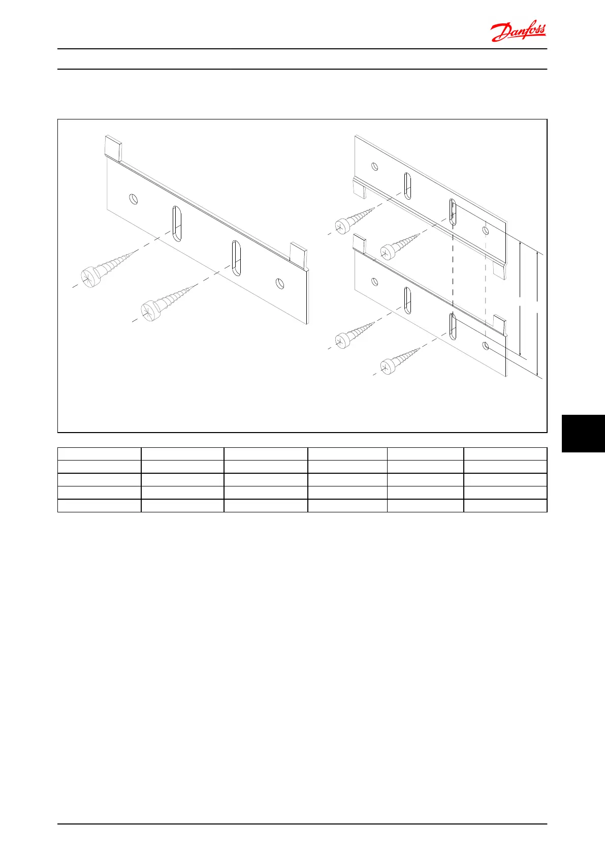
130BA844.10
130BA845.10
A
B
Step 1 Step 2
Position the lower bracket and mount it with screws. Do not tighten the
screws completely since this will make it difficult to mount the frequency
converter.
Measure distance A or B, and position the upper bracket, but
do not tighten it. See dimensions below
Frame size A5 B1 B2 B3 B4
IP 55/66 21/55/66 21/55/66 21/55/66 21/55/66
A [mm] 480 535 705 730 820
B [mm] 495 550 720 745 835
Ordering number 130B1080 130B1081 130B1082 130B1083 130B1084
Options and Accessories FC 300 Design Guide
MG.33.BD.02 - VLT
®
is a registered Danfoss trademark 251
10
10

Table of Contents

Other manuals for Danfoss VLT AutomationDrive

Questions and Answers:

Question and Answer IconNeed help?

Do you have a question about the Danfoss VLT AutomationDrive and is the answer not in the manual?

Danfoss VLT AutomationDrive Specifications

General IconGeneral
Supply Voltage3 x 200-240 V ±10% 3 x 380-500 V ±10% 3 x 525-600 V ±10%
EnclosureIP20
Output Power Range0.25 kW - 1.5 MW
Communication ProtocolsModbus RTU
Protection FeaturesOvercurrent, Overvoltage, Undervoltage, Short circuit, Ground fault, Motor overload
Ambient Temperature Range-10°C to +50°C (14°F to 122°F)

Related product manuals