8.6 Control Cables and Terminals
8.6.1 Access to Control Terminals
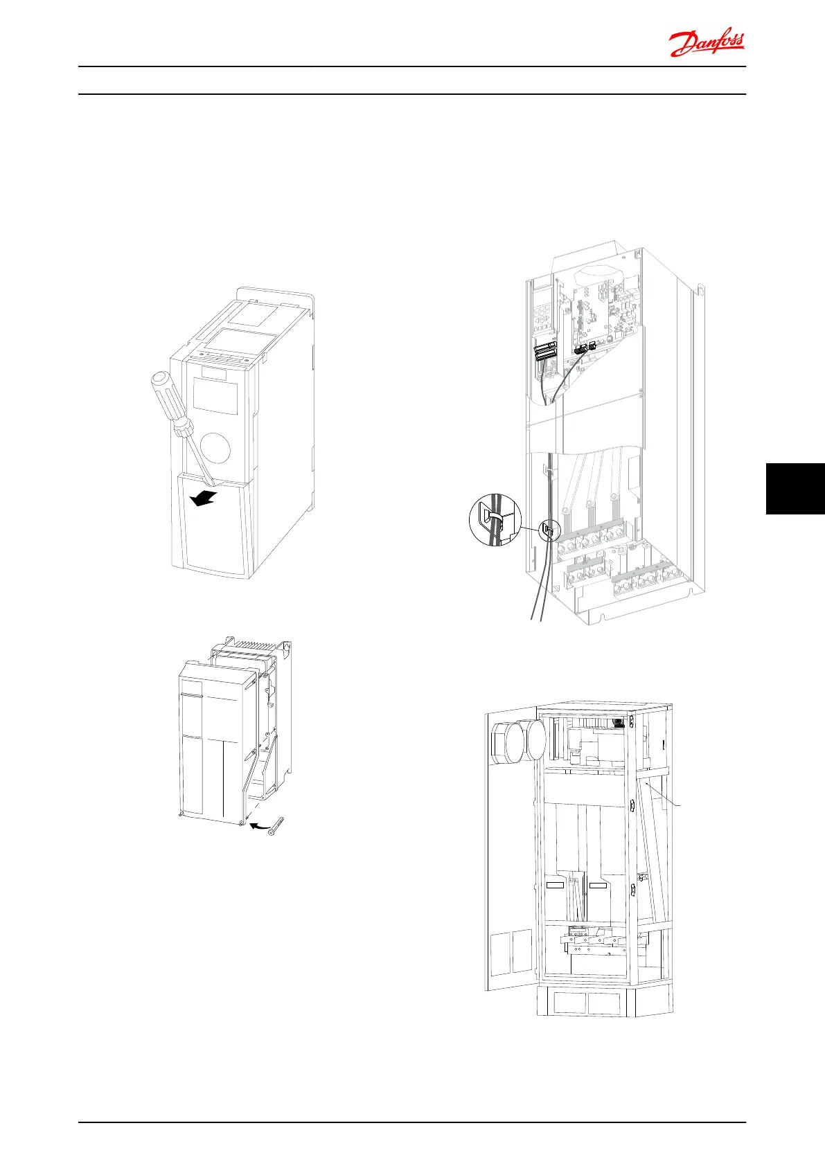
All terminals to the control cables are located underneath
the terminal cover on the front of the frequency converter.
Remove the terminal cover by means of a screwdriver (see
illustration).
Illustration 8.51 Frame sizes A1, A2, A3,B3, B4, C3 and C4
Illustration 8.52 Frame sizes A5, B1, B2, C1 and C2
8.6.2
Control Cable Routing
Tie down all control wires to the designated control cable
routing as shown in the picture. Remember to connect the
shields in a proper way to ensure optimum electrical
immunity.
Fieldbus connection
Connections are made to the relevant options on the
control card. For details see the relevant fieldbus
instruction. The cable must be placed in the provided path
inside the frequency converter and tied down together
with other control wires (see illustrations).
176FA246.10
U/T1 96
-DC 88
R/L1 91
S/L2 92
T/L3 93
+DC 89
V/T2 97
W/13
Illustration 8.53 Control card wiring path for the D3. Control
card wiring for the D1, D2, D4, E1 and E2 use the same path.
Illustration 8.54 Control card wiring path for the F1/F3. Control
card wiring for the F2/F4 use the same path.
Electrical Installation FC 300 Design Guide
MG.33.BD.02 - VLT
®
is a registered Danfoss trademark 209
8 8

 Loading...


