3.2.4
Control Structure in VVC
plus
Advanced Vector Control
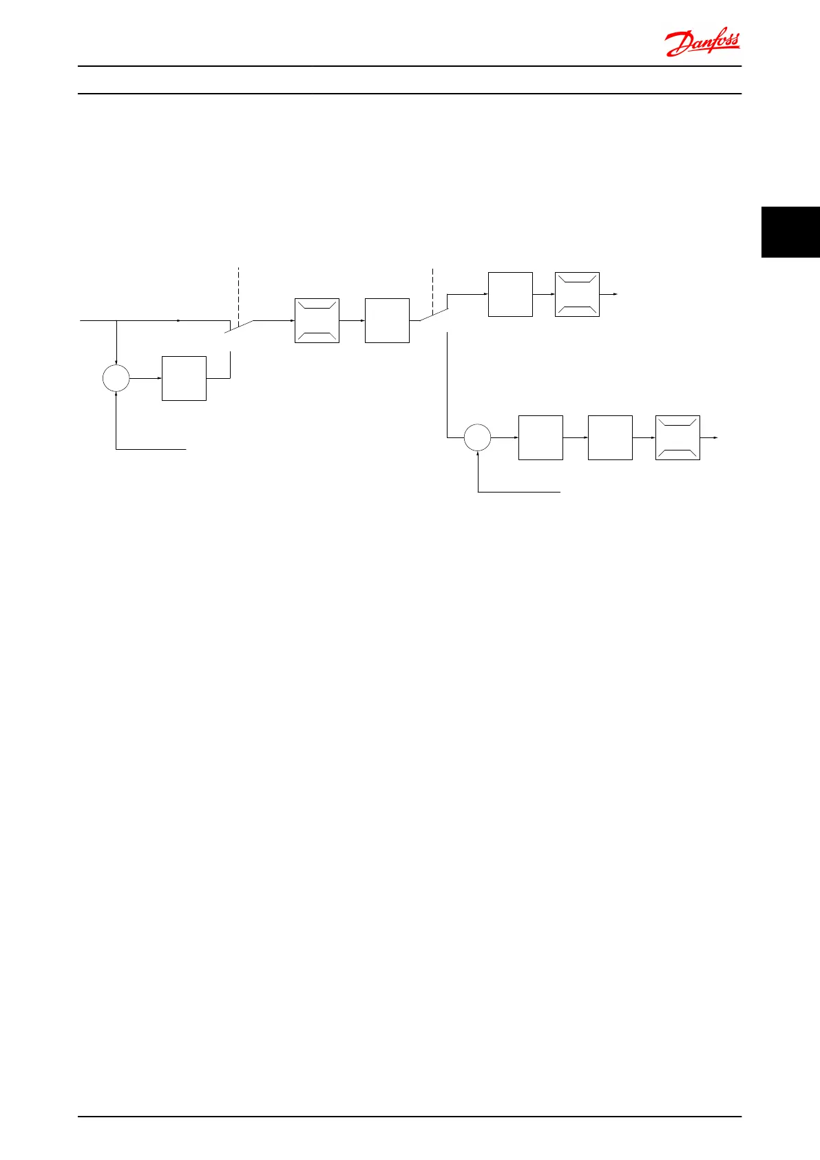
Control structure in VVC
plus
open loop and closed loop configurations:
+
_
+
_
Cong. mode
Ref.
Process
P 1-00
High
+f max.
Low
-f max.
P 4-11
Motor speed
low limit (RPM)
P 4-12
Motor speed
low limit (Hz)
P 4-13
Motor speed
high limit (RPM)
P 4-14
Motor speed
high limit (Hz)
Motor
controller
Ramp
Speed
PID
P 7-20 Process feedback
1 source
P 7-22 Process feedback
2 source
P 7-00 Speed PID
feedback source
P 1-00
Cong. mode
P 4-19
Max. output freq.
-f max.
Motor
controller
P 4-19
Max. output freq.
+f max.
P 3-**
P 7-0*
130BA055.10
In the configuration shown in Illustration 3.3, 1-01 Motor Control Principle is set to “VVC
plus
[1]” and 1-00 Configuration Mode is
set to “Speed open loop [0]”. The resulting reference from the reference handling system is received and fed through the
ramp limitation and speed limitation before being sent to the motor control. The output of the motor control is then
limited by the maximum frequency limit.
If 1-00 Configuration Mode is set to “Speed closed loop [1]” the resulting reference will be passed from the ramp limitation
and speed limitation into a speed PID control. The Speed PID control parameters are located in the parameter group 7-0*.
The resulting reference from the Speed PID control is sent to the motor control limited by the frequency limit.
Select “Process [3]” in 1-00 Configuration Mode to use the process PID control for closed loop control of e.g. speed or
pressure in the controlled application. The Process PID parameters are located in parameter group 7-2* and 7-3*.
Introduction to FC 300 FC 300 Design Guide
MG.33.BD.02 - VLT
®
is a registered Danfoss trademark 19
3
3

 Loading...


