8.2.4 Shielding against Electrical Noise
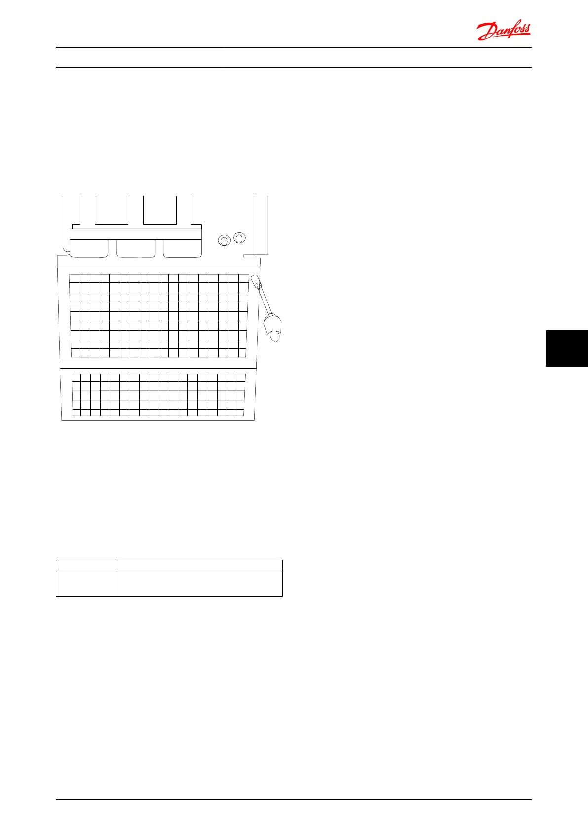
Before mounting the mains power cable, mount the EMC
metal cover to ensure best EMC performance.
NOTE: The EMC metal cover is only included in units with
an RFI filter.
Illustration 8.50 Mounting of EMC shield.
8.2.5
External Fan Supply
Frame size D,E,F
In case the frequency converter is supplied by DC or if the
fan must run independently of the power supply, an
external power supply can be applied. The connection is
made on the power card.
Terminal No.
Function
100, 101
102, 103
Auxiliary supply S, T
Internal supply S, T
The connector located on the power card provides the
connection of line voltage for the cooling fans. The fans
are connected from factory to be supplied form a common
AC line (jumpers between 100-102 and 101-103). If external
supply is needed, the jumpers are removed and the supply
is connected to terminals 100 and 101. A 5 Amp fuse
should be used for protection. In UL applications this
should be LittleFuse KLK-5 or equivalent.
Electrical Installation FC 300 Design Guide
MG.33.BD.02 - VLT
®
is a registered Danfoss trademark 189
8 8

 Loading...


