7.2.5 Terminal Locations - Frame size F
NOTE
The F frames have four different sizes, F1, F2, F3 and F4. The F1 and F2 consist of an inverter cabinet on the right and
rectifier cabinet on the left. The F3 and F4 have an additional options cabinet left of the rectifier cabinet. The F3 is an F1
with an additional options cabinet. The F4 is an F2 with an additional options cabinet.
Terminal locations - Frame size F1 and F3
.0 [.0]
54.4[2.1]
169.4 [6.7]
284.4 [11.2]
407.3 [16.0]
522.3 [20.6]
637.3 [25.1]
287.4 [11.3]
253.1 [10.0]
.0 [.0]
.0 [.0]
339.4 [13.4]
287.4 [11.3]
.0 [.0]
339.4 [13.4]
308.3 [12.1]
465.6 [18.3]
465.6 [18.3]
198.1[7.8]
234.1 [9.2]
282.1 [11.1]
318.1 [12.5]
551.0 [21.7]
587.0 [23.1]
635.0 [25.0]
671.0 [26.4]
44.40 [1.75]
244.40 [9.62]
204.1 [8.0]
497.1 [19.6]
572.1 [22.5]
180.3 [7.1]
129.1 [5.1]
130BA849.10
2
2
1
3
3
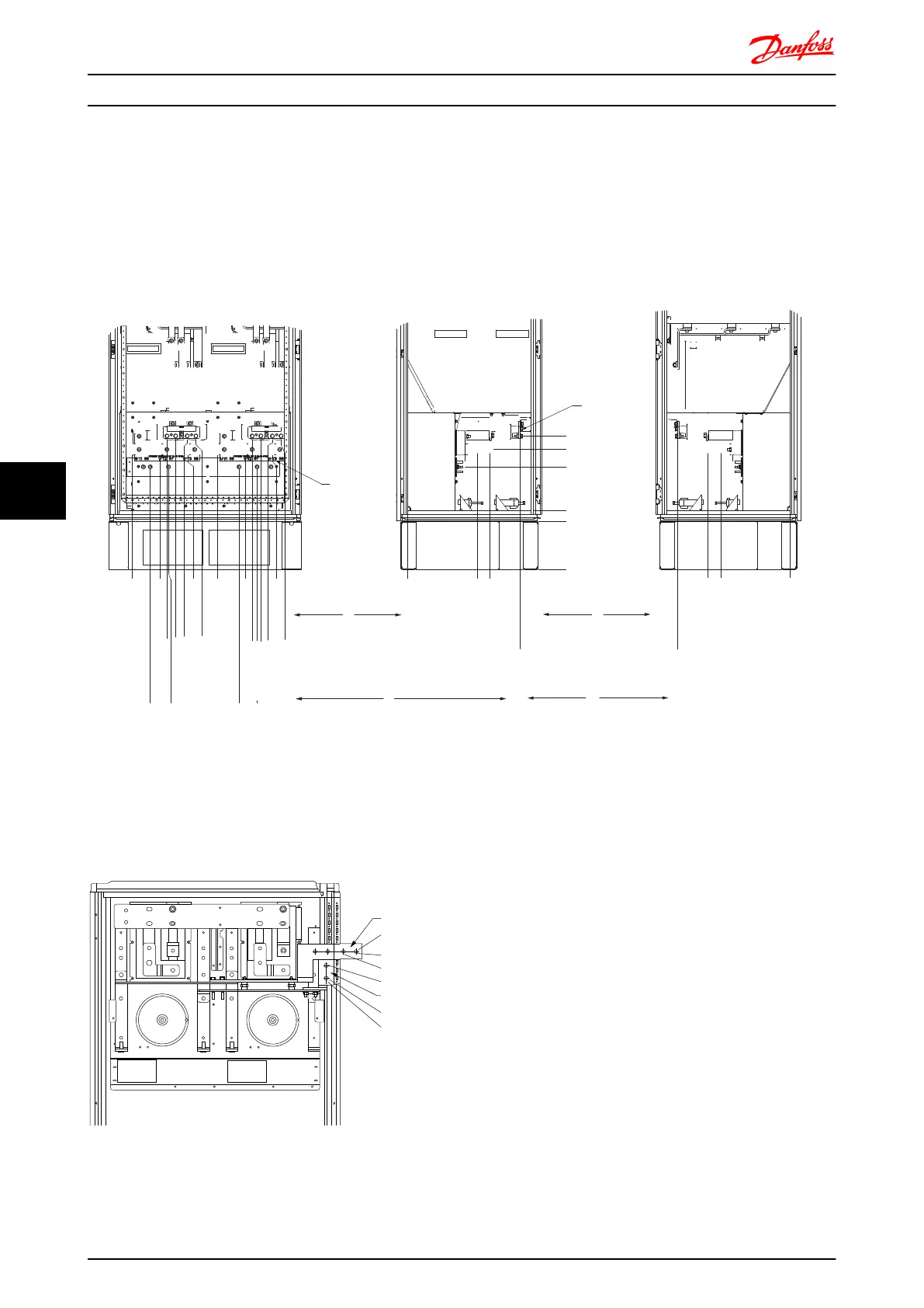
3
Illustration 7.26 Terminal locations - Inverter Cabinet - F1 and F3 (front, left and right side view). The gland plate is 42mm below .0 level.
1) Earth ground bar
2) Motor terminals
3) Brake terminals
S1 F1
F1
DC ‘-’
DC ‘+’
1739.1
805.0
765.0
1694.1
1654.1
710.0
130BB377.10
Illustration 7.27 Terminal Locations - Regen Terminals - F1 and
F3
Mechanical Installation - ... FC 300 Design Guide
142 MG.33.BD.02 - VLT
®
is a registered Danfoss trademark
77

 Loading...


