Transmitter
96 97 9998
91 92 93 95
50
12
L1 L2
L1
PEL3
W PEVU
F1
L2
L3
N
PE
130BA175.11
18
53
37
55
54
M
3
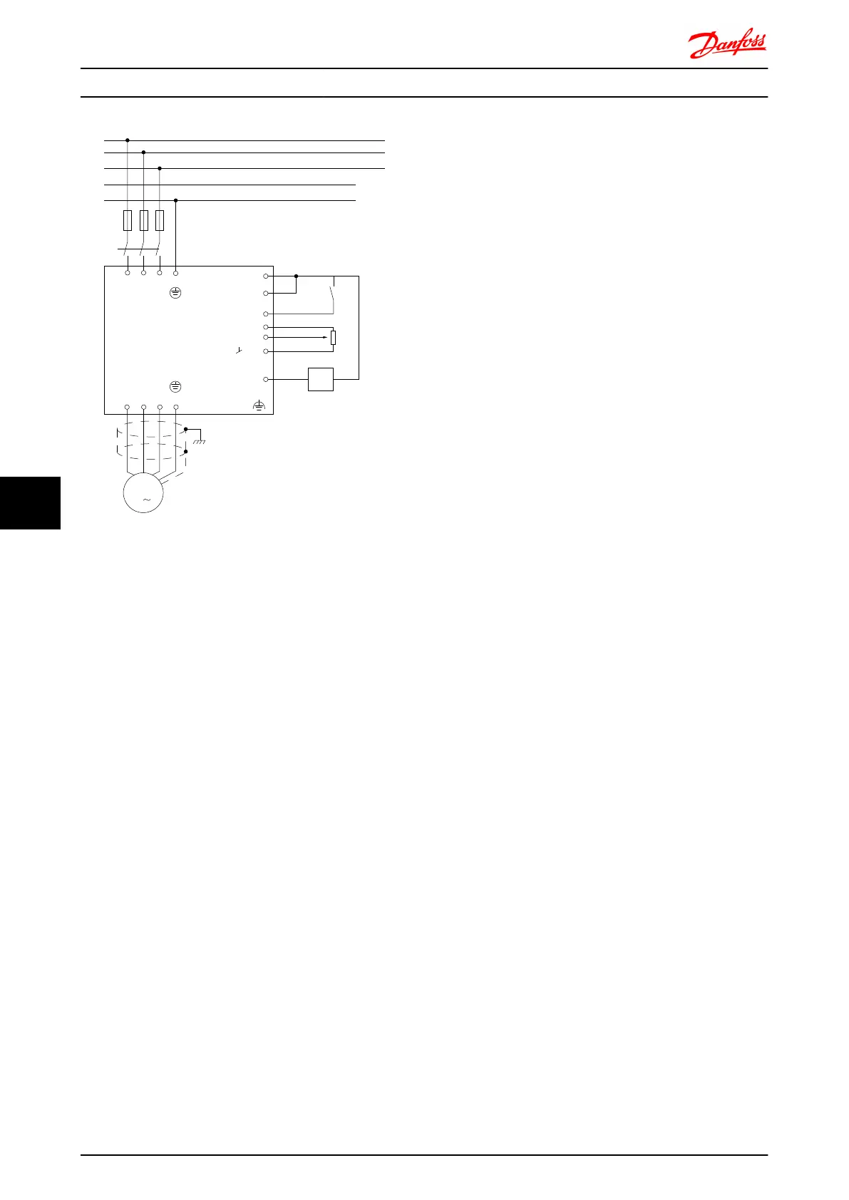
Illustration 8.64 Electrical Connection Diagram.
8.9.2
Use of EMC-Correct Cables
Danfoss recommends braided screened/armoured cables to
optimise EMC immunity of the control cables and the EMC
emission from the motor cables.
The ability of a cable to reduce the in- and outgoing
radiation of electric noise depends on the transfer
impedance (Z
T
). The screen of a cable is normally designed
to reduce the transfer of electric noise; however, a screen
with a lower transfer impedance (Z
T
) value is more
effective than a screen with a higher transfer impedance
(Z
T
).
Transfer impedance (Z
T
) is rarely stated by cable manufac-
turers but it is often possible to estimate transfer
impedance (Z
T
) by assessing the physical design of the
cable.
Electrical Installation FC 300 Design Guide
222 MG.33.BD.02 - VLT
®
is a registered Danfoss trademark
88

 Loading...


