EasyManuals Logo
Home>Danfoss>DC Drives>VLT AutomationDrive

Danfoss VLT AutomationDrive Design Guide

Danfoss VLT AutomationDrive
281 pages
To Next Page IconTo Next Page
To Previous Page IconTo Previous Page
Page #169 background imageLoading...
Page #169 background image
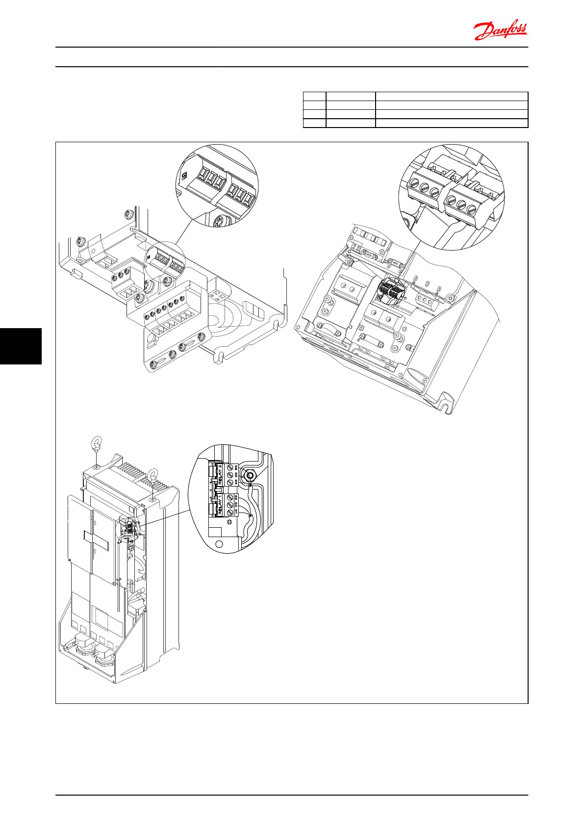
8.1.4 Relay Connection
To set relay output, see parameter group 5-4* Relays.
No. 01 - 02 make (normally open)
01 - 03 break (normally closed)
04 - 05 make (normally open)
04 - 06 break (normally closed)
130BA029.12
Relay2
Relay1
35 36
311
130BA215.10
RELAY 1
RELAY 2
9
9
6
03 02 01
90 05 04
Terminals for relay connection
(Frame sizes A1, A2 and A3).
Terminals for relay connection
(Frame sizes A5, B1 and B2).
130BA391.12
RELAY 1 RELAY 2
06 05 04 03 02 01
DC+
Terminals for relay connection
(Frame sizes C1 and C2).
Electrical Installation FC 300 Design Guide
168 MG.33.BD.02 - VLT
®
is a registered Danfoss trademark
88

Table of Contents

Other manuals for Danfoss VLT AutomationDrive

Questions and Answers:

Question and Answer IconNeed help?

Do you have a question about the Danfoss VLT AutomationDrive and is the answer not in the manual?

Danfoss VLT AutomationDrive Specifications

General IconGeneral
BrandDanfoss
ModelVLT AutomationDrive
CategoryDC Drives
LanguageEnglish

Related product manuals