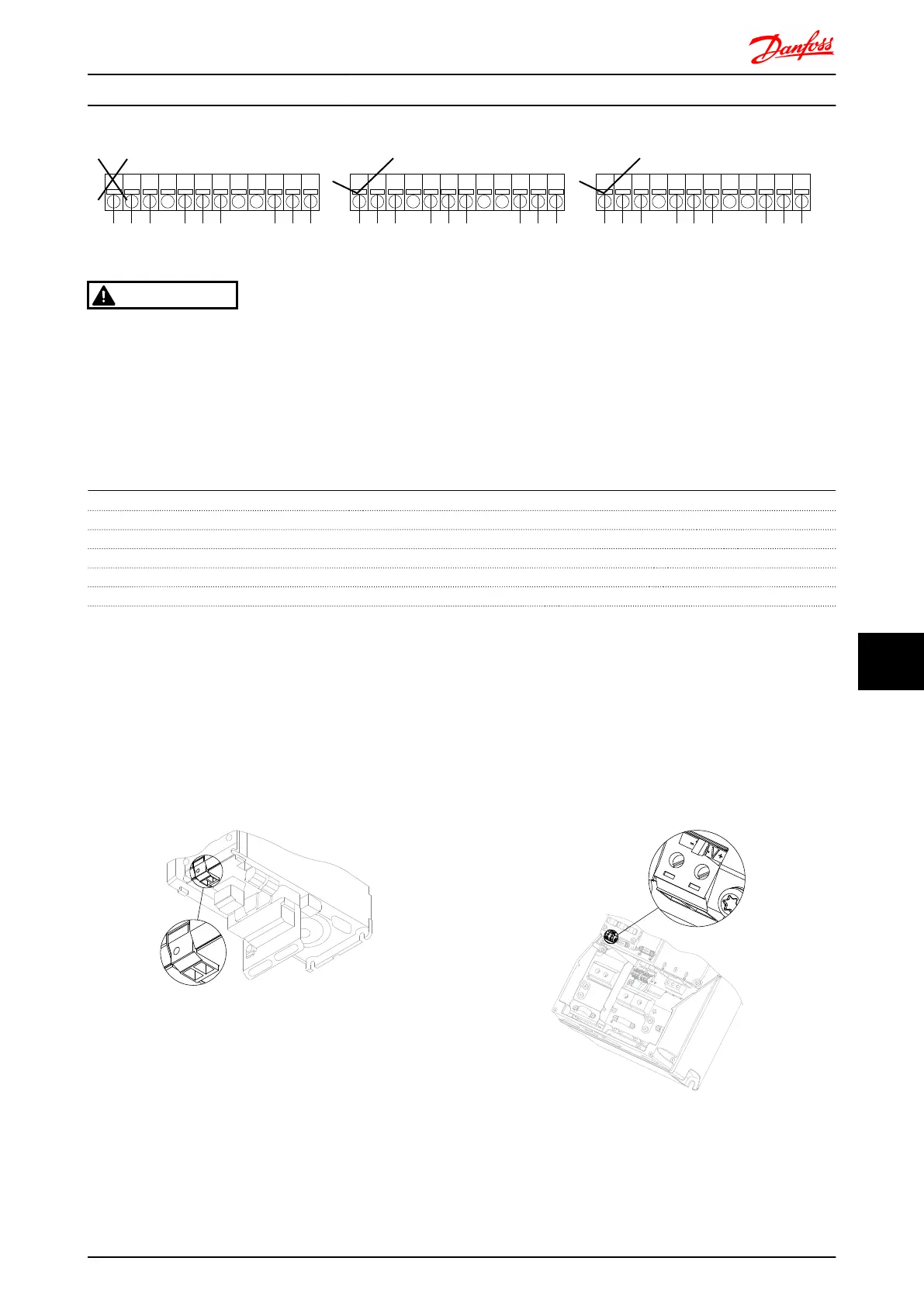
NC NC NC NC NC NC NC NC NC
PELVPELVPELV
1 102 3 4 5 6 7 8 9 1211
PELVLIVE
PAR T
LIVE
PAR T
1 102 3 4 5 6 7 8 9 1211 1 102 3 4 5 6 7 8 9 1211
130BA176.10
LIVE
PAR T
LIVE
PAR T
LIVE
PAR T
WARNING
Do not combine 24/ 48V systems with high voltage
systems.
10.6 24V Back-Up Option MCB 107
External 24V DC Supply
An external 24V DC supply can be installed for low-voltage supply to the control card and any option card installed. This
enables full operation of the LCP (including the parameter setting) without connection to mains.
External 24V DC supply specification:
Input voltage range 24V DC ±15 % (max. 37V in 10 sec.)
Max. input current 2.2A
Average input current for FC 302 0.9 A
Max cable length 75 m
Input capacitance load < 10uF
Power-up delay < 0.6 sec.
The inputs are protected.
Terminal numbers:
Terminal 35: - external 24V DC supply.
Terminal 36: + external 24V DC supply.
Follow these steps:
1. Remove the LCP or Blind Cover
2. Remove the Terminal Cover
3. Remove the Cable Decoupling Plate and the
plastic cover underneath
4. Insert the 24V DC Back-up External Supply Option
in the Option Slot
5. Mount the Cable Decoupling Plate
6. Attach the Terminal Cover and the LCP or Blind
Cover.
When MCB 107, 24V back-up option is supplying the control circuit, the internal 24V supply is automatically disconnected.
Illustration 10.7 Connection to 24V back-up supply on frame
sizes A2 and A3.
9
9
6
311
130BA216.10
35 36
Illustration 10.8 Connection to 24V back-up supply on frame
sizes A5, B1, B2, C1 and C2.
Options and Accessories FC 300 Design Guide
MG.33.BD.02 - VLT
®
is a registered Danfoss trademark 243
10
10

 Loading...


