11 RS-485 Installation and Set-up
11.1 Overview
RS485 is a two-wire bus interface compatible with multi-
drop network topology, i.e. nodes can be connected as a
bus, or via drop cables from a common trunk line. A total
of 32 nodes can be connected to one network segment.
Repeaters divide network segments. Please note that each
repeater functions as a node within the segment in which
it is installed. Each node connected within a given network
must have a unique node address, across all segments.
Terminate each segment at both ends, using either the
termination switch (S801) of the frequency converters or a
biased termination resistor network. Always use screened
twisted pair (STP) cable for bus cabling, and always follow
good common installation practice.
Low-impedance earth connection of the screen at every
node is important, including at high frequencies. Thus,
connect a large surface of the screen to earth, for example
with a cable clamp or a conductive cable gland. It may be
necessary to apply potential-equalizing cables to maintain
the same earth potential throughout the network. Partic-
ularly in installations with long cables.
To prevent impedance mismatch, always use the same
type of cable throughout the entire network. When
connecting a motor to the frequency converter, always use
screened motor cable.
Cable: Screened twisted pair (STP)
Impedance: 120Ω
Cable length: Max. 1200m (including drop lines)
Max. 500m station-to-station
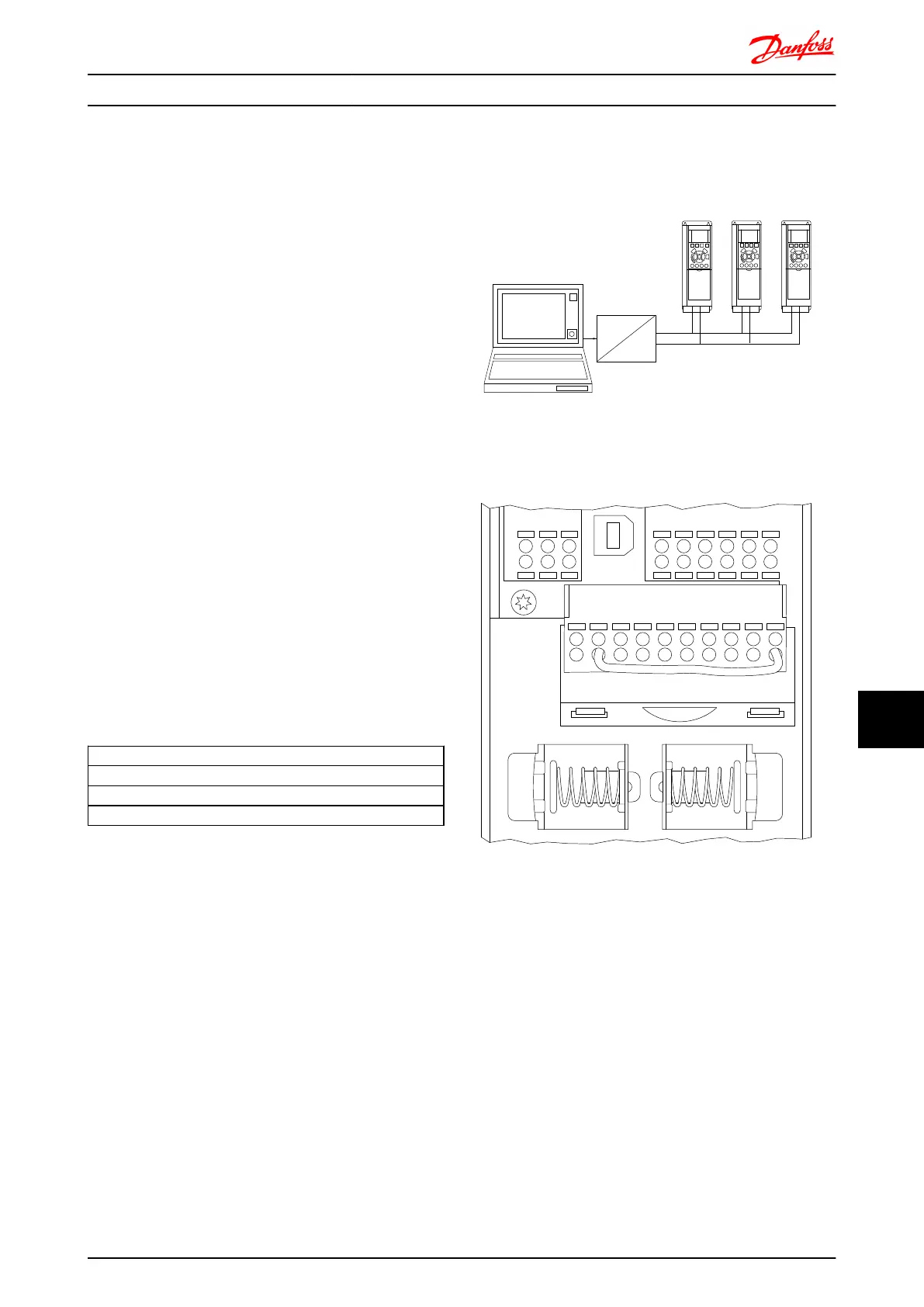
11.2 Network Connection
One or more frequency converters can be connected to a
control (or master) using the RS485 standardized interface.
Terminal 68 is connected to the P signal (TX+, RX+), while
terminal 69 is connected to the N signal (TX-,RX-). See
drawings in 8.8.3 Earthing of Screened Control Cables
If more than one frequency converter is connected to a
master, use parallel connections.
130BA060.11
68 69 68 69 68 69
RS 485
RS 232
USB
+
-
In order to avoid potential equalizing currents in the
screen, earth the cable screen via terminal 61, which is
connected to the frame via an RC-link.
130BB021.10
12 13 18 19 27 29 32
33 20 37
Remove jumper to enable Safe Stop
61 68 69 39 42 50 53 54 55
Illustration 11.1 Control Card Terminals
11.3 Bus Termination
The RS485 bus must be terminated by a resistor network
at both ends. For this purpose, set switch S801 on the
control card for "ON".
For more information, see 8.6.4 Switches S201, S202, and
S801 .
Communication protocol must be set to 8-30 Protocol.
RS-485 Installation and Set... FC 300 Design Guide
MG.33.BD.02 - VLT
®
is a registered Danfoss trademark 255
11
11

 Loading...


