EasyManuals Logo

Danfoss VLT AutomationDrive Design Guide

Danfoss VLT AutomationDrive
281 pages
To Next Page IconTo Next Page
To Previous Page IconTo Previous Page
Page #213 background imageLoading...
Page #213 background image
130BT311.10
Illustration 8.59 3.
130BT306.10
8.6.6
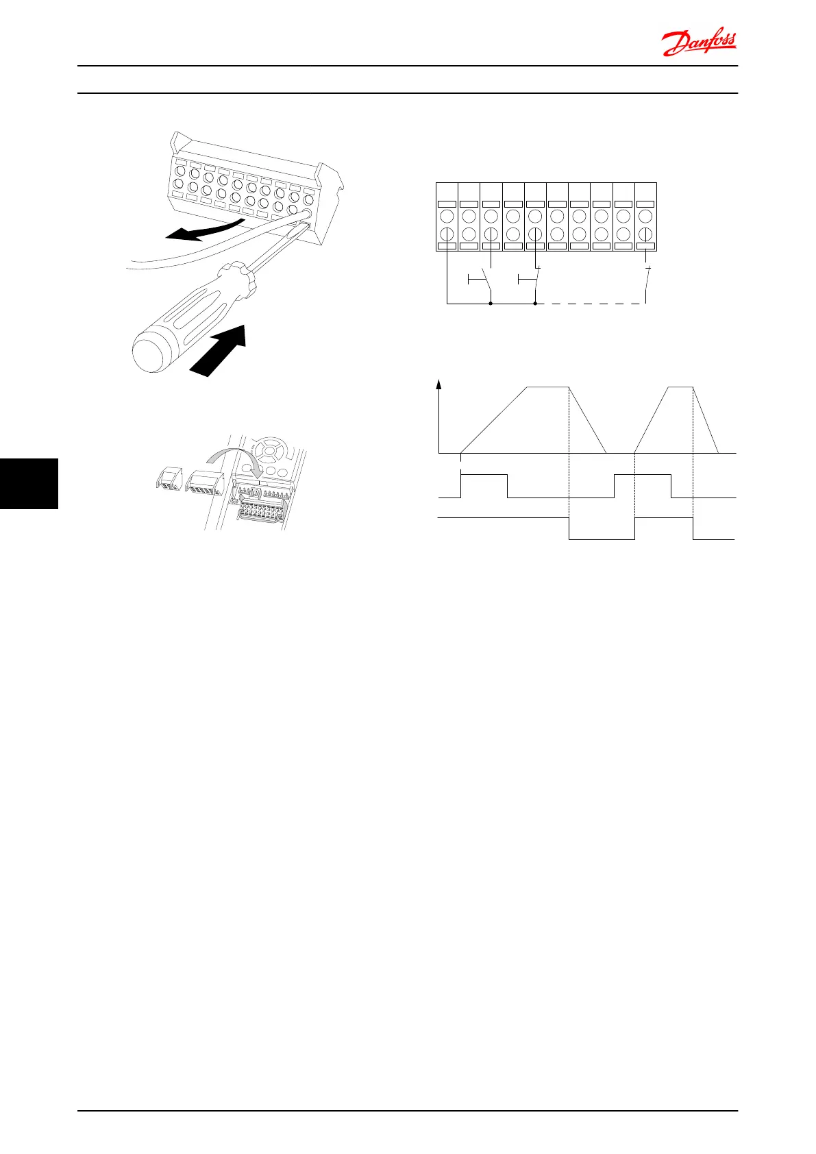
Basic Wiring Example
1. Mount terminals from the accessory bag to the
front of the frequency converter.
2. Connect terminals 18, 27 and 37 (FC 302 only) to
+24V (terminal 12/13)
Default settings:
18 = Start, 5-10 Terminal 18 Digital Input [9]
27 = Stop inverse, 5-12 Terminal 27 Digital Input [6]
37 = safe stop inverse
12 13 18 37
130BA156.12
322719 29 33 20
P 5 - 12 [6]
P 5 - 10[9]
+24V
Speed
Start Stop inverse Safe Stop
Start (18)
Start (27)
Electrical Installation FC 300 Design Guide
212 MG.33.BD.02 - VLT
®
is a registered Danfoss trademark
88

Table of Contents

Other manuals for Danfoss VLT AutomationDrive

Questions and Answers:

Question and Answer IconNeed help?

Do you have a question about the Danfoss VLT AutomationDrive and is the answer not in the manual?

Danfoss VLT AutomationDrive Specifications

General IconGeneral
Supply Voltage3 x 200-240 V ±10% 3 x 380-500 V ±10% 3 x 525-600 V ±10%
EnclosureIP20
Output Power Range0.25 kW - 1.5 MW
Communication ProtocolsModbus RTU
Protection FeaturesOvercurrent, Overvoltage, Undervoltage, Short circuit, Ground fault, Motor overload
Ambient Temperature Range-10°C to +50°C (14°F to 122°F)

Related product manuals