176FA281.10
0[0.0]
0[0.0]0[0.0] ABCD
F
E
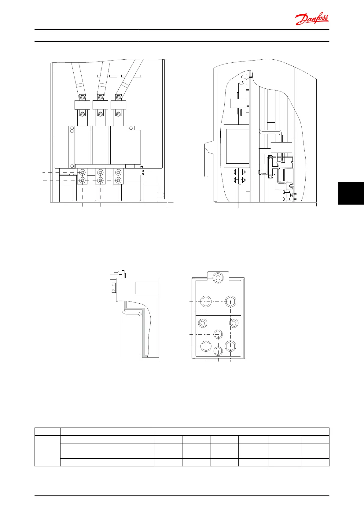
Illustration 7.24 IP00 enclosure power connections positions of disconnect switch
Note that the power cables are heavy and difficult to
bend. Consider the optimum position of the frequency
converter for ensuring easy installation of the cables.
Each terminal allows use of up to 4 cables with cable lugs
or use of standard box lug. Earth is connected to relevant
termination point in the frequency converter.
104[4.1]
35[1.4]
10[0.4]
0[0.0]
0[0.0]
40[1.6]
78[3.1]
0[0.0]
26[1.0]
26[1.0]
176FA271.10
B B
B B
A
A
Illustration 7.25 Terminal in details
NOTE
Power connections can be made to positions A or B
Frame size Unit type Dimension for disconnect terminal
E2
IPOO/CHASSIS A B C D E F
250/315kW (400V) AND
355/450-500/630KW (690V)
381 (15.0) 245 (9.6) 334 (13.1) 423 (16.7) 256 (10.1) N/A
315/355-400/450kW (400V) 383 (15.1) 244 (9.6) 334 (13.1) 424 (16.7) 109 (4.3) 149 (5.8)
Mechanical Installation - ... FC 300 Design Guide
MG.33.BD.02 - VLT
®
is a registered Danfoss trademark 141
7 7

 Loading...


