EasyManuals Logo

Danfoss VLT AutomationDrive Design Guide

Danfoss VLT AutomationDrive
281 pages
To Next Page IconTo Next Page
To Previous Page IconTo Previous Page
Page #141 background imageLoading...
Page #141 background image
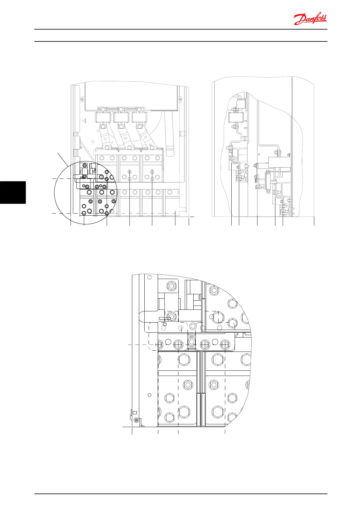
Terminal locations - Frame size E2
Take the following position of the terminals into consideration when designing the cable access.
176FA280.10
585[23.0]
518[20.4]
405[15.9]
68[2.7]
0[0.0]
186[7.3]
0[0.0]
0[0.0]
181[7.1]
293[11.5]
409[16.1]
371[14.6]
280[11.0]
192[7.6]
154[6.1]
17[0.7]
A
R/L1 91
9
S/L2 92
U/T1 96 V/T2 97
T/L3 93
W/T3 98
FASTENER TORQUE M8 9.6 Nm (7 FT-LB) FASTENER TORQUE M8 9.6 Nm (7 FT-LB)
Illustration 7.22 IP00 enclosure power connection positions
176FA282.10
0(0.0)
47(1.9)
83(3.3)
131(5.2)
167(6.6)
0(0.0)
147(5.8)
A A A A
019Nm (14 F)
9
A
R 81
Illustration 7.23 IP00 enclosure power connection positions
Mechanical Installation - ... FC 300 Design Guide
140 MG.33.BD.02 - VLT
®
is a registered Danfoss trademark
77

Table of Contents

Other manuals for Danfoss VLT AutomationDrive

Questions and Answers:

Question and Answer IconNeed help?

Do you have a question about the Danfoss VLT AutomationDrive and is the answer not in the manual?

Danfoss VLT AutomationDrive Specifications

General IconGeneral
Supply Voltage3 x 200-240 V ±10% 3 x 380-500 V ±10% 3 x 525-600 V ±10%
EnclosureIP20
Output Power Range0.25 kW - 1.5 MW
Communication ProtocolsModbus RTU
Protection FeaturesOvercurrent, Overvoltage, Undervoltage, Short circuit, Ground fault, Motor overload
Ambient Temperature Range-10°C to +50°C (14°F to 122°F)

Related product manuals