EasyManuals Logo

Danfoss VLT AutomationDrive Design Guide

Danfoss VLT AutomationDrive
281 pages
To Next Page IconTo Next Page
To Previous Page IconTo Previous Page
Page #140 background imageLoading...
Page #140 background image
0[0.0]
B
C
D
0[0.0]
F
E
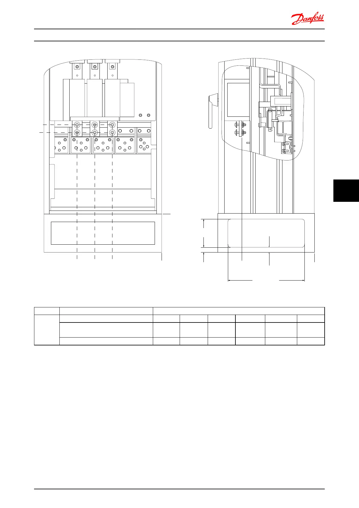
FASTENER TORQUE: M8 9.6 Nm [7 FT-LB] FASTENER TORQUE: M10 19 Nm [14 FT-LB]
R/L1 91 S/L2 92 T/L3 93
V/T2 97/T1 96 V/T3 9
19 Nm [14FT-LB]
0[0.0]
144[5.7]
26[1.0]
26[1.0]
391[15.4]
A
176FA279.10
Illustration 7.21 IP21 (NEMA type 1) and IP54 (NEMA type 12) enclosure power connection position of disconnect switch
Frame size
Unit type Dimension for disconnect terminal
E1
IP54/IP21 UL AND NEMA1/NEMA12
250/315 kW (400V) AND 355/450-500/630
KW (690V)
381 (15.0) 253 (9.9) 253 (9.9) 431 (17.0) 562 (22.1) N/A
315/355-400/450 kW (400V) 371 (14.6) 371 (14.6) 341 (13.4) 431 (17.0) 431 (17.0) 455 (17.9)
Mechanical Installation - ... FC 300 Design Guide
MG.33.BD.02 - VLT
®
is a registered Danfoss trademark 139
7 7

Table of Contents

Other manuals for Danfoss VLT AutomationDrive

Questions and Answers:

Question and Answer IconNeed help?

Do you have a question about the Danfoss VLT AutomationDrive and is the answer not in the manual?

Danfoss VLT AutomationDrive Specifications

General IconGeneral
Supply Voltage3 x 200-240 V ±10% 3 x 380-500 V ±10% 3 x 525-600 V ±10%
EnclosureIP20
Output Power Range0.25 kW - 1.5 MW
Communication ProtocolsModbus RTU
Protection FeaturesOvercurrent, Overvoltage, Undervoltage, Short circuit, Ground fault, Motor overload
Ambient Temperature Range-10°C to +50°C (14°F to 122°F)

Related product manuals