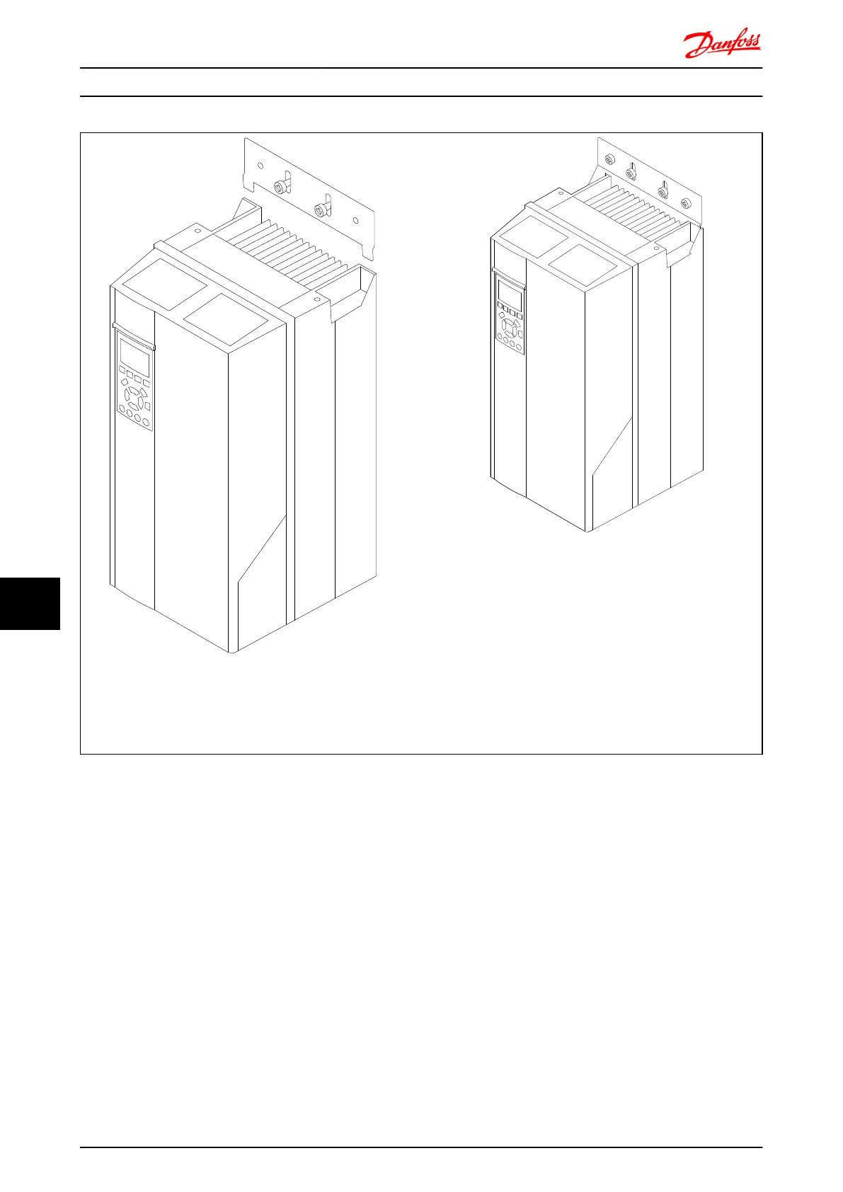
EasyManuals Logo

Danfoss VLT AutomationDrive Design Guide

Danfoss VLT AutomationDrive
281 pages
To Next Page IconTo Next Page
To Previous Page IconTo Previous Page
Page #253 background imageLoading...
Page #253 background image
130BA846.10
130BA847.10
Step 3 Step 4
Place the frequency converter in the lower bracket, lift the upper one. When the
frequency converter is in place, lower the upper bracket.
Now tighten the screws. For extra security, drill and
mount screws in all holes.
Options and Accessories FC 300 Design Guide
252 MG.33.BD.02 - VLT
®
is a registered Danfoss trademark
10
10

Table of Contents

Other manuals for Danfoss VLT AutomationDrive

Questions and Answers:

Question and Answer IconNeed help?

Do you have a question about the Danfoss VLT AutomationDrive and is the answer not in the manual?

Danfoss VLT AutomationDrive Specifications

General IconGeneral
Supply Voltage3 x 200-240 V ±10% 3 x 380-500 V ±10% 3 x 525-600 V ±10%
EnclosureIP20
Output Power Range0.25 kW - 1.5 MW
Communication ProtocolsModbus RTU
Protection FeaturesOvercurrent, Overvoltage, Undervoltage, Short circuit, Ground fault, Motor overload
Ambient Temperature Range-10°C to +50°C (14°F to 122°F)

Related product manuals