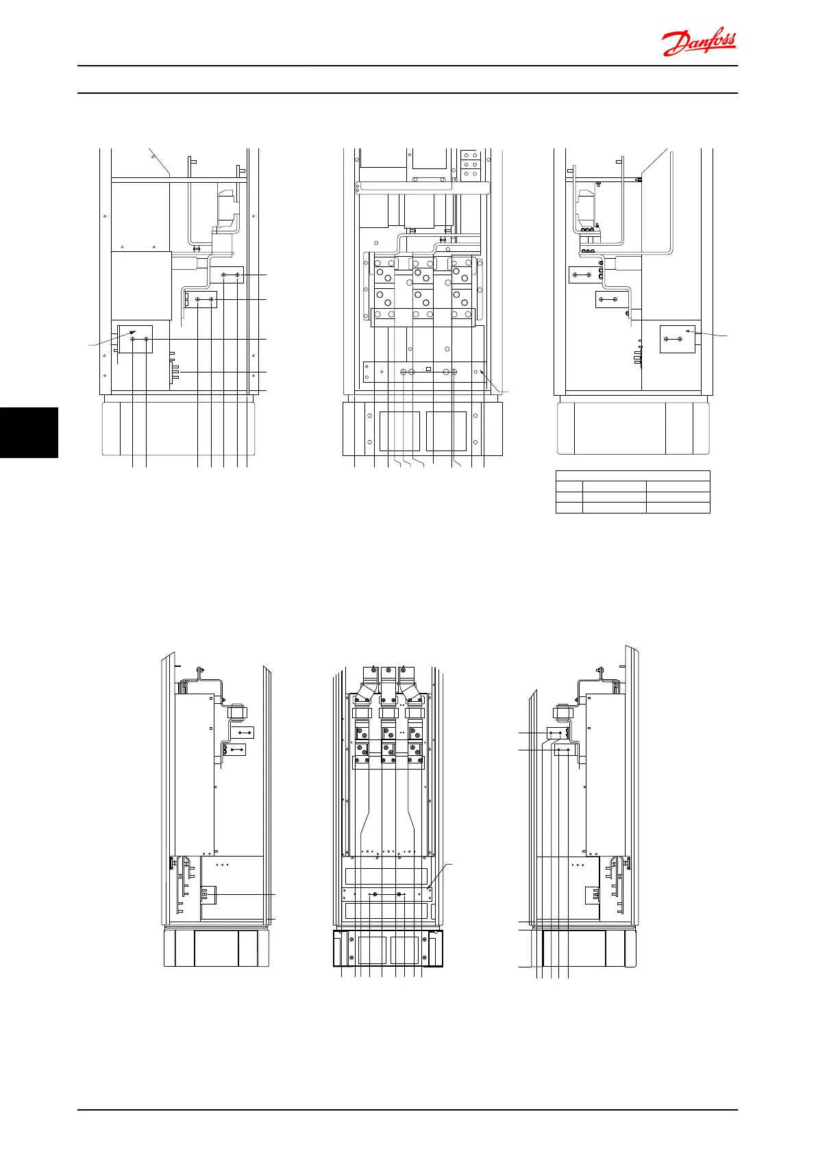
Terminal locations - Rectifier (F1, F2, F3 and F4)
74.6 [2.9]
0.0 [0.0]
125.8 [4.95]
218.6 [8.61]
293.6 [11.56]
362.6 [14.28]
437.6 [17.23]
149.6 [5.89]
486.6 [19.16]
183.4 [7.22]
373.4 [14.70]
0.0 [0.00]
70.4 [2.77]
193.9 [7.64]
343.1 [13.51]
38.1 [1.50]
0.0 [0.00]
90.1 [3.55]
136.6 [5.38]
188.6 [7.42]
B
A
435.5 [17.15]
LOAD SHARE LOCATION
DIM F1/F2 F3/F4
A 380.5 [14.98] 29.4 [1.16]
B 432.5 [17.03] 81.4 [3.20]
1
2
3
130BA848.11
CH22 CH22
R/L1 91 S/L2 92
FASTENER TORQUE: M8 9.6 Nm (7 FT-LB)
T/L3 93
FASTENER TORQUE: M10 19 Nm (14 FT-LB)
FASTENER TORQUE: M10 19 Nm (14 FT-LB)
DC 89
FASTENER TORQUE: M10 19 Nm (14 FT-LB)
DC 89
CH22 CH22 CH22 CH22
CTI25MB CTI25MB
AUXAUXAUXAUXAU X
Illustration 7.30 Terminal locations - Rectifier (Left side, front and right side view). The gland plate is 42mm below .0 level.
1) Loadshare Terminal (-)
2) Earth ground bar
3) Loadshare Terminal (+)
Terminal locations - Options Cabinet (F3 and F4)
1
0.0[0.00]
76.4[3.01]
128.4[5.05]
119.0[4.69]
171.0[6.73]
294[11.60]
344.0[13.54]
3639[14.33]
438.9[17.28]
75.3[2.96]
150.3[5.92]
3639[6.06]
219.6[18.65]
0.0[0.00]
244.4[9.62]
244.4[1.75]
939.0[36.97]
1031.4[40.61]
0.0[0.00]
134.6[5.30]
130BA851.10
0.0[1.75]
Illustration 7.31 Terminal locations - Options Cabinet (Left side, front and right side view). The gland plate is 42mm below .0 level.
1) Earth ground bar
Mechanical Installation - ... FC 300 Design Guide
144 MG.33.BD.02 - VLT
®
is a registered Danfoss trademark
77

 Loading...


