EasyManuals Logo

Danfoss VLT AutomationDrive Design Guide

Danfoss VLT AutomationDrive
281 pages
To Next Page IconTo Next Page
To Previous Page IconTo Previous Page
Page #160 background imageLoading...
Page #160 background image
130BA263.10
95
M
A
INS
+DC
BR-
BR+
U
V
W
91
92
93
L1
L2
L3
RELAY 1 RELAY 2
+DC
BR-
BR+
U
V
W
MAINS
L1 L2 L3
91 92 93
RELAY 1 RELAY 2
99
- LC -
130BA264.10
Mains connector frame size A4/A5 (IP 55/66)
L 1
L 2
L 3
91
92
93
130BT336.10
130BT335.10
When disconnector is used (frame size A4/A5) the PE must
be mounted on the left side of the drive.
130BT332.10
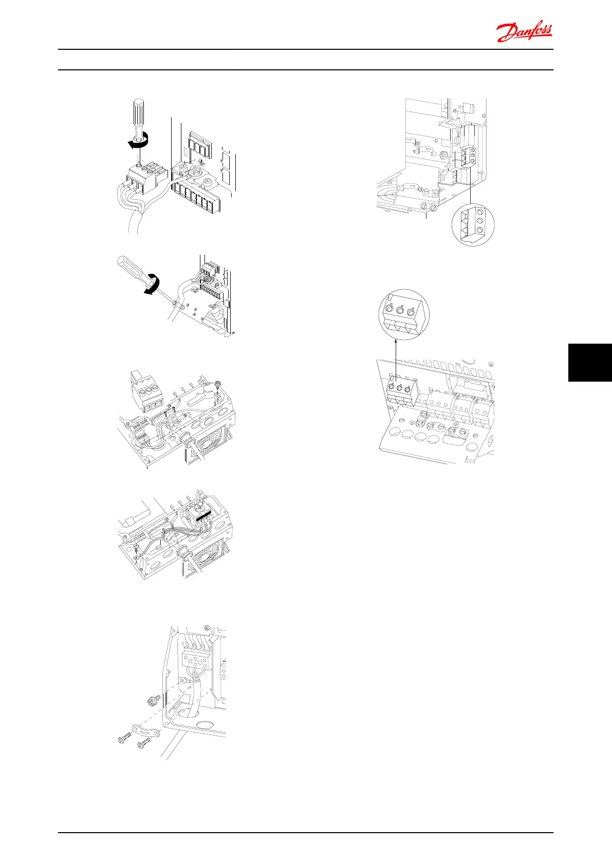
Illustration 8.1 Mains connection frame sizes B1 and B2 (IP 21/
NEMA Type 1 and IP 55/66/ NEMA Type 12).
130BA725.10
Illustration 8.2 Mains connection size B3 (IP20).
L1 91
L2 92
L3 93
L1 91
L2 92
L3 93
U 96
V 97
W 98
DC-88
DC+89
R-81
R+82
130BA714.10
95
99
Illustration 8.3 Mains connection size B4 (IP20).
Electrical Installation FC 300 Design Guide
MG.33.BD.02 - VLT
®
is a registered Danfoss trademark 159
8 8

Table of Contents

Other manuals for Danfoss VLT AutomationDrive

Questions and Answers:

Question and Answer IconNeed help?

Do you have a question about the Danfoss VLT AutomationDrive and is the answer not in the manual?

Danfoss VLT AutomationDrive Specifications

General IconGeneral
Supply Voltage3 x 200-240 V ±10% 3 x 380-500 V ±10% 3 x 525-600 V ±10%
EnclosureIP20
Output Power Range0.25 kW - 1.5 MW
Communication ProtocolsModbus RTU
Protection FeaturesOvercurrent, Overvoltage, Undervoltage, Short circuit, Ground fault, Motor overload
Ambient Temperature Range-10°C to +50°C (14°F to 122°F)

Related product manuals