Make the screen connections with the largest possible
surface area (cable clamp). This is done by using the
supplied installation devices within the frequency
converter.
Cable-length and cross-section:
The frequency converter has been EMC tested with a given
length of cable. Keep the motor cable as short as possible
to reduce the noise level and leakage currents.
Switching frequency:
When frequency converters are used together with Sine-
wave filters to reduce the acoustic noise from a motor, the
switching frequency must be set according to the
instruction in 14-01 Switching Frequency.
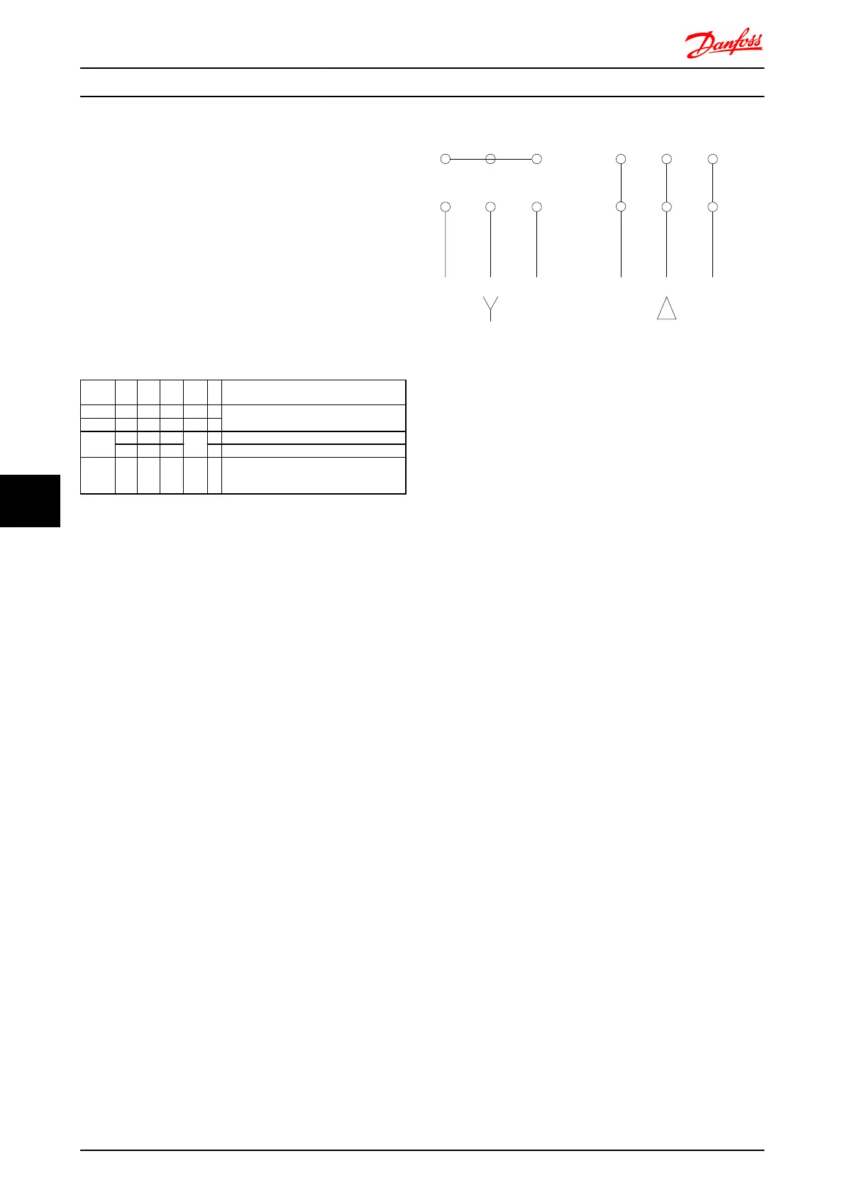
Term.
no.
96 97 98 99
U V W
PE
1)
Motor voltage 0-100% of mains voltage.
3 wires out of motor
U1 V1 W1
PE
1)
Delta-connected
W2 U2 V2 6 wires out of motor
U1 V1 W1
PE
1)
Star-connected U2, V2, W2
U2, V2 and W2 to be interconnected
separately.
1)
Protected Earth Connection
CAUTION
In motors without phase insulation paper or other
insulation reinforcement suitable for operation with
voltage supply (such as a frequency converter), fit a Sine-
wave filter on the output of the frequency converter.
U V W
175ZA114.10
VU W
96 97 98
96 97 98
Electrical Installation FC 300 Design Guide
170 MG.33.BD.02 - VLT
®
is a registered Danfoss trademark
88

 Loading...


