* F10/F11/F12/F13 Only
91-1
92-1
93-1
91-2
92-2
93-2
S1
T1
R1
S2
T2
R2
95
Rectifier 1
Rectifier 2
Inverter1
F8/F9
Inverter2
F10/F11
Inverter3
F12/F13
130BB758.10
91-1
92-1
93-1
91-2
92-2
93-2
S1
T1
R1
S2
T2
R2
95
Rectifier 1
Rectifier 2
Inverter1
F8/F9
Inverter2
F10/F11
Inverter3
F12/F13
91-1
92-1
93-1
91-2
92-2
93-2
95
Rectifier 1
Rectifier 2
Inverter1
Inverter2
F10/F11
Inverter3
F12/F13
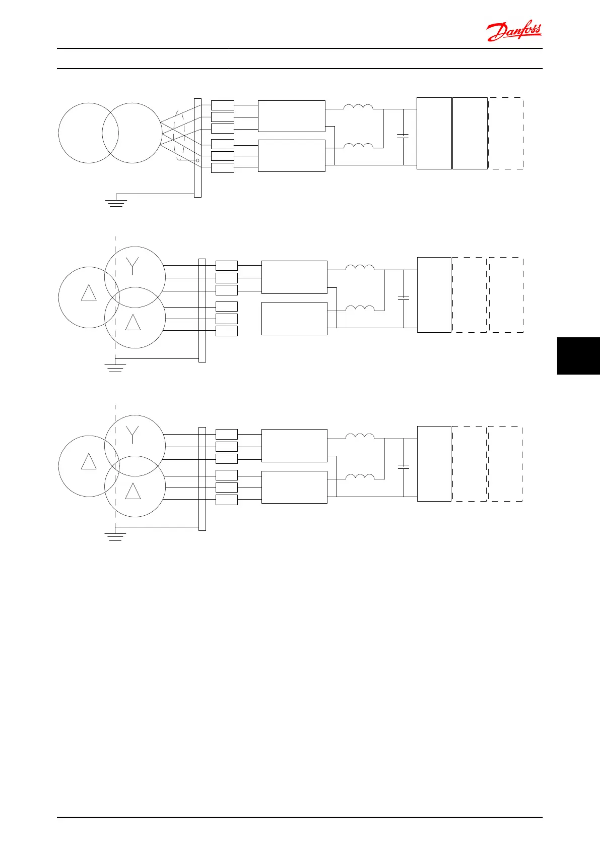
A
B
C
Illustration 8.43
A) 6-Pulse Connection
1), 2), 3)
B) Modified 6-Pulse Connection
2), 3), 4)
C) 12-Pulse Connection
3), 5)
Notes:
1) Parallel connection shown. A single three phase cable may be used with sufficient carrying capability. Shorting busbars
must be installed.
2) 6-pulse connection eliminates the harmonics reduction benefits of the 12-pulse rectifier.
3) Suitable for IT and TN mains connection.
4) In the unlikely event that one of the 6-pulse modular rectifiers becomes inoperable, it is possible to operate the drive at
reduced load with a single 6-pulse rectifier. Contact factory for reconnection details.
5) No paralleling of mains cabling is shown here.
Electrical Installation FC 300 Design Guide
MG.33.BD.02 - VLT
®
is a registered Danfoss trademark 181
8 8

 Loading...


