EasyManuals Logo

Danfoss VLT AutomationDrive Design Guide

Danfoss VLT AutomationDrive
281 pages
To Next Page IconTo Next Page
To Previous Page IconTo Previous Page
Page #188 background imageLoading...
Page #188 background image
R/L1 91 S/L2 92 T/L3 93
CFD30J3
130BB699.10
3
6
5
2
1
4
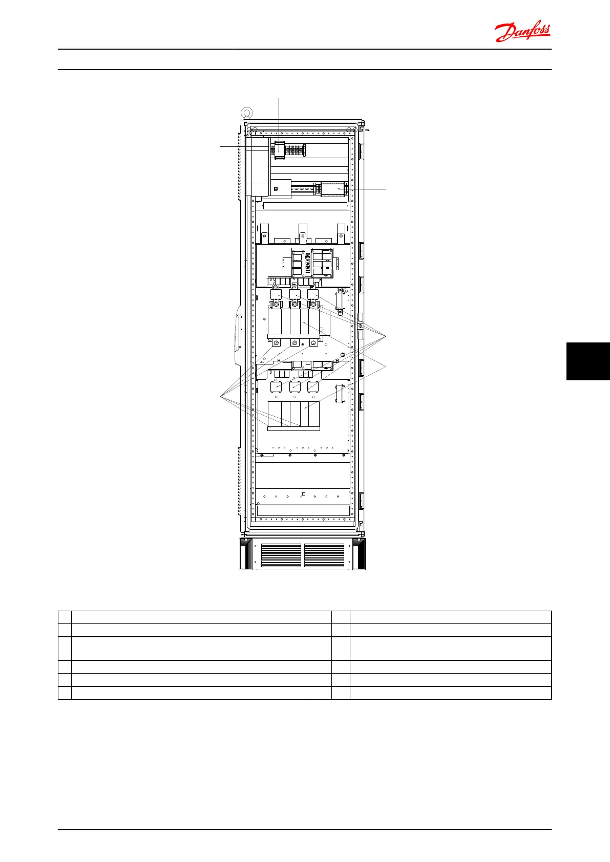
Illustration 8.48 Options Cabinet, frame size F9
1)
Pilz Relay Terminal 4) Safety Relay Coil Fuse with Pilz Relay
2) RCD or IRM Terminal See fuse tables for part numbers
3) Mains/6 phase 5) Line Fuses, (6 pieces)
R1 S1 T1 R2 S2 T2 See fuse tables for part numbers
91-1 92-1 93-1 91-2 92-2 93-2 6) 2 x 3-phase manual disconnect
L1-1 L2-1 L3-1 L1-2 L2-2 L3-2
Electrical Installation FC 300 Design Guide
MG.33.BD.02 - VLT
®
is a registered Danfoss trademark 187
8 8

Table of Contents

Other manuals for Danfoss VLT AutomationDrive

Questions and Answers:

Question and Answer IconNeed help?

Do you have a question about the Danfoss VLT AutomationDrive and is the answer not in the manual?

Danfoss VLT AutomationDrive Specifications

General IconGeneral
Supply Voltage3 x 200-240 V ±10% 3 x 380-500 V ±10% 3 x 525-600 V ±10%
EnclosureIP20
Output Power Range0.25 kW - 1.5 MW
Communication ProtocolsModbus RTU
Protection FeaturesOvercurrent, Overvoltage, Undervoltage, Short circuit, Ground fault, Motor overload
Ambient Temperature Range-10°C to +50°C (14°F to 122°F)

Related product manuals