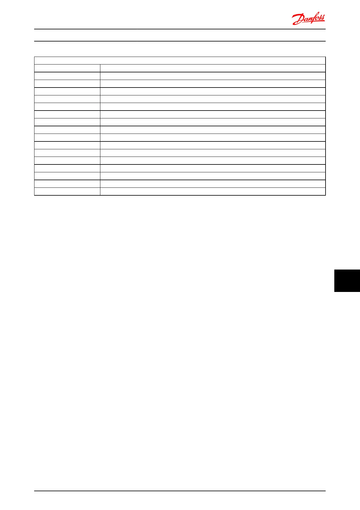
Holding registers
Register Number Description
00001-00006 Reserved
00007 Last error code from an FC data object interface
00008 Reserved
00009 Parameter index*
00010-00990 000 parameter group (parameters 001 through 099)
01000-01990 100 parameter group (parameters 100 through 199)
02000-02990 200 parameter group (parameters 200 through 299)
03000-03990 300 parameter group (parameters 300 through 399)
04000-04990 400 parameter group (parameters 400 through 499)
... ...
49000-49990 4900 parameter group (parameters 4900 through 4999)
50000 Input data: frequency converter control word register (CTW).
50010 Input data: Bus reference register (REF).
... ...
50200 Output data: frequency converter status word register (STW).
50210 Output data: frequency converter main actual value register (MAV).
* Used to specify the index number to be used when accessing an indexed parameter.
RS-485 Installation and Set... FC 300 Design Guide
MG.33.BD.02 - VLT
®
is a registered Danfoss trademark 265
11
11

 Loading...


