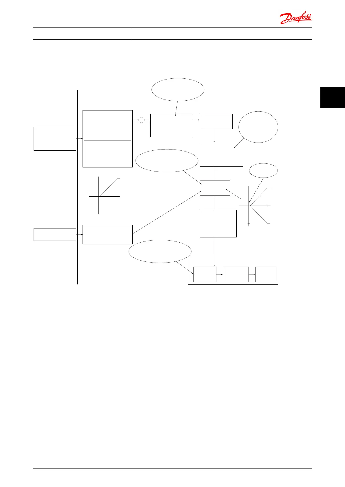
Case 1: Positive Reference with Dead band, Digital input to trigger reverse
This Case shows how Reference input with limits inside Min – Max limits clamps.
500
1
10
V
V
500
1
10
-500
130BA187.11
+
Analog input 53
Low reference 0 RPM
High reference 500 RPM
Low voltage 1V
High voltage 10V
Ext. source 1
Range:
0,0% (0 RPM)
100,0% (500 RPM)
100,0% (500 RPM)
Ext. reference
Range:
0,0% (0 RPM)
500 RPM 10V
Ext. Reference
Absolute
0 RPM 1V
Reference
algorithm
Reference
100,0% (500 RPM)
0,0% (0 RPM)
Range:
Limited to:
0%- +100%
(0 RPM- +500 RPM)
Limited to: -200%- +200%
(-1000 RPM- +1000 RPM)
Reference is scaled
according to min
max reference giving a
speed.!!!
Scale to
speed
+500 RPM
-500 RPM
Range:
Speed
setpoint
Motor
control
Range:
-200 RPM
+200 RPM
Motor
Digital input 19
Low No reversing
High Reversing
Limits Speed Setpoint
according to min max speed.!!!
Motor PID
RPM
RPM
Dead band
Digital input
General Reference
parameters:
Reference Range: Min - Max
Minimum Reference: 0 RPM (0,0%)
Maximum Reference: 500 RPM (100,0%)
General Motor
parameters:
Motor speed direction:Both directions
Motor speed Low limit: 0 RPM
Motor speed high limit: 200 RPM
Introduction to FC 300 FC 300 Design Guide
MG.33.BD.02 - VLT
®
is a registered Danfoss trademark 27
3
3

 Loading...


