1.21.0 1.4
30
10
20
100
60
40
50
1.81.6 2.0
2000
500
200
400
300
1000
600
t [s]
175ZA052.12
f
OUT
=
2 x f
M,N
f
OUT
= 0.
2 x f
M,N
f
OUT
=
1 x f
M,N
(par. 1-23)
I
M,N
(par. 1-24)
I
M
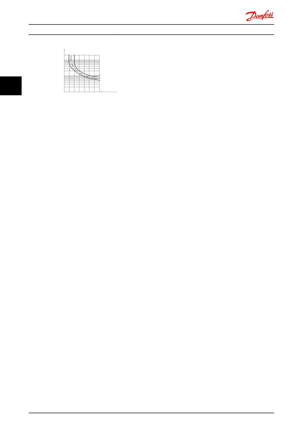
Illustration 3.15 Figure ETR: The X-axis shows the ratio between
I
motor
and I
motor
nominal. The Y- axis shows the time in seconds
before the ETR cut of and trips the drive. The curves show the
characteristic nominal speed, at twice the nominal speed and at
0,2 x the nominal speed.
At lower speed the ETR cuts of at lower heat due to less cooling
of the motor. In that way the motor are protected from being
over heated even at low speed. The ETR feature is calculating
the motor temperature based on actual current and speed. The
calculated temperature is visible as a read out parameter in
16-18 Motor Thermal in the FC 300.
Introduction to FC 300 FC 300 Design Guide
50 MG.33.BD.02 - VLT
®
is a registered Danfoss trademark
3
3

 Loading...


