Voltage mode Switch S201/switch S202 = OFF (U)
Voltage level FC 301: 0 to + 10/ FC 302: -10 to +10V (scaleable)
Input resistance, R
i
approx. 10 kΩ
Max. voltage ± 20V
Current mode Switch S201/switch S202 = ON (I)
Current level 0/4 to 20 mA (scaleable)
Input resistance, R
i
approx. 200 Ω
Max. current 30 mA
Resolution for analog inputs 10 bit (+ sign)
Accuracy of analog inputs Max. error 0.5% of full scale
Bandwidth FC 301: 20 Hz/ FC 302: 100 Hz
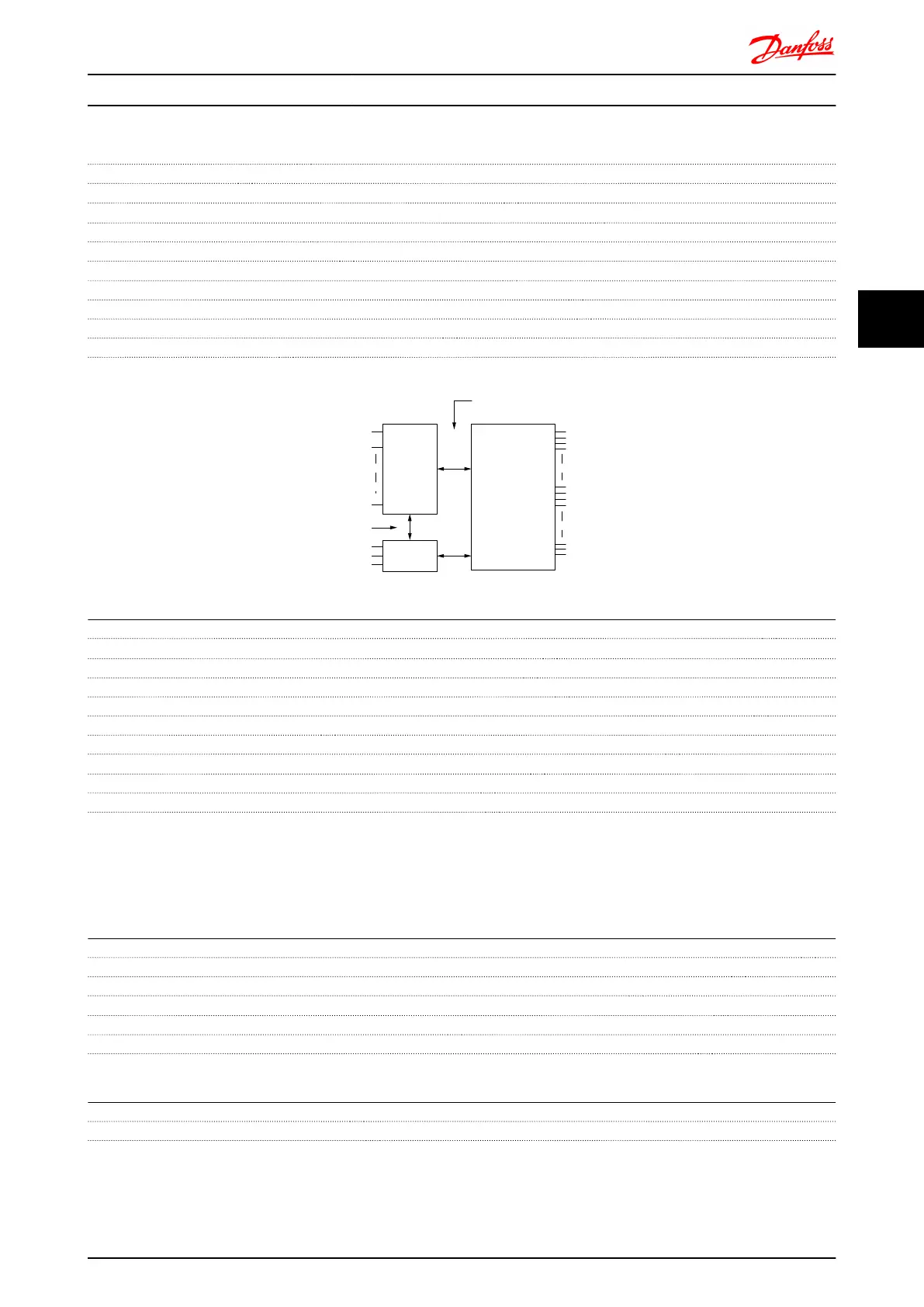
The analog inputs are galvanically isolated from the supply voltage (PELV) and other high-voltage terminals.
Mains
Functional
isolation
PELV isolation
Motor
DC-Bus
High
voltage
Control
+24V
RS485
18
37
130BA117.10
Pulse/encoder inputs:
Programmable pulse/encoder inputs 2/1
Terminal number pulse/encoder 29
1)
, 33
2)
/ 32
3)
, 33
3)
Max. frequency at terminal 29, 32, 33 110kHz (Push-pull driven)
Max. frequency at terminal 29, 32, 33 5kHz (open collector)
Min. frequency at terminal 29, 32, 33 4Hz
Voltage level see section on Digital input
Maximum voltage on input 28V DC
Input resistance, R
i
approx. 4kΩ
Pulse input accuracy (0.1 - 1kHz) Max. error: 0.1% of full scale
Encoder input accuracy (1 - 11 kHz) Max. error: 0.05 % of full scale
The pulse and encoder inputs (terminals 29, 32, 33) are galvanically isolated from the supply voltage (PELV) and other high-
voltage terminals.
1)
FC 302 only
2)
Pulse inputs are 29 and 33
3)
Encoder inputs: 32 = A, and 33 = B
Analog output:
Number of programmable analog outputs 1
Terminal number 42
Current range at analog output 0/4 - 20mA
Max. load GND - analog output 500Ω
Accuracy on analog output Max. error: 0.5% of full scale
Resolution on analog output 12 bit
The analogue output is galvanically isolated from the supply voltage (PELV) and other high-voltage terminals.
Control card, RS-485 serial communication:
Terminal number 68 (P,TX+, RX+), 69 (N,TX-, RX-)
Terminal number 61 Common for terminals 68 and 69
The RS-485 serial communication circuit is functionally separated from other central circuits and galvanically isolated from the
supply voltage (PELV).
FC 300 Selection FC 300 Design Guide
MG.33.BD.02 - VLT
®
is a registered Danfoss trademark 87
4 4

 Loading...


