The display is divided into 3 sections:
Top section
(a) shows the status when in status mode, or up to 2
variables when not in Status mode, and if there is an
alarm/warning.
The number of the active setup (selected as the active set-
up in parameter 0-10 Active Set-up) is shown. When
programming in another setup than the active setup, the
number of the setup being programmed appears to the
right in brackets.
Middle section
(b) shows up to 5 variables with related unit, regardless of
status. If an alarm/warning occurs, the warning is shown
instead of the variables.
Bottom section
(c) always shows the state of the frequency converter in
status mode.
Press [Status] to toggle between 3 status readout displays.
Operating variables with dierent formatting are shown in
each status screen.
Several values or measurements can be linked to each of
the shown operating variables.
Dene the values/measurements to be shown via:
•
Parameter 0-20 Display Line 1.1 Small
•
Parameter 0-21 Display Line 1.2 Small
•
Parameter 0-22 Display Line 1.3 Small
•
Parameter 0-23 Display Line 2 Large
•
Parameter 0-24 Display Line 3 Large
which can be accessed via [Quick Menu], Q3 Function Set-
ups, Q3-1 General Settings, Q3-13 Display Settings.
Each value/measurement readout parameter selected in
parameter 0-20 Display Line 1.1 Small to
parameter 0-24 Display Line 3 Large has its own scale and
number of digits after a possible decimal point. Larger
numeric values are shown with few digits after the decimal
point.
Ex.: Current readout
5.25 A; 15.2 A 105 A.
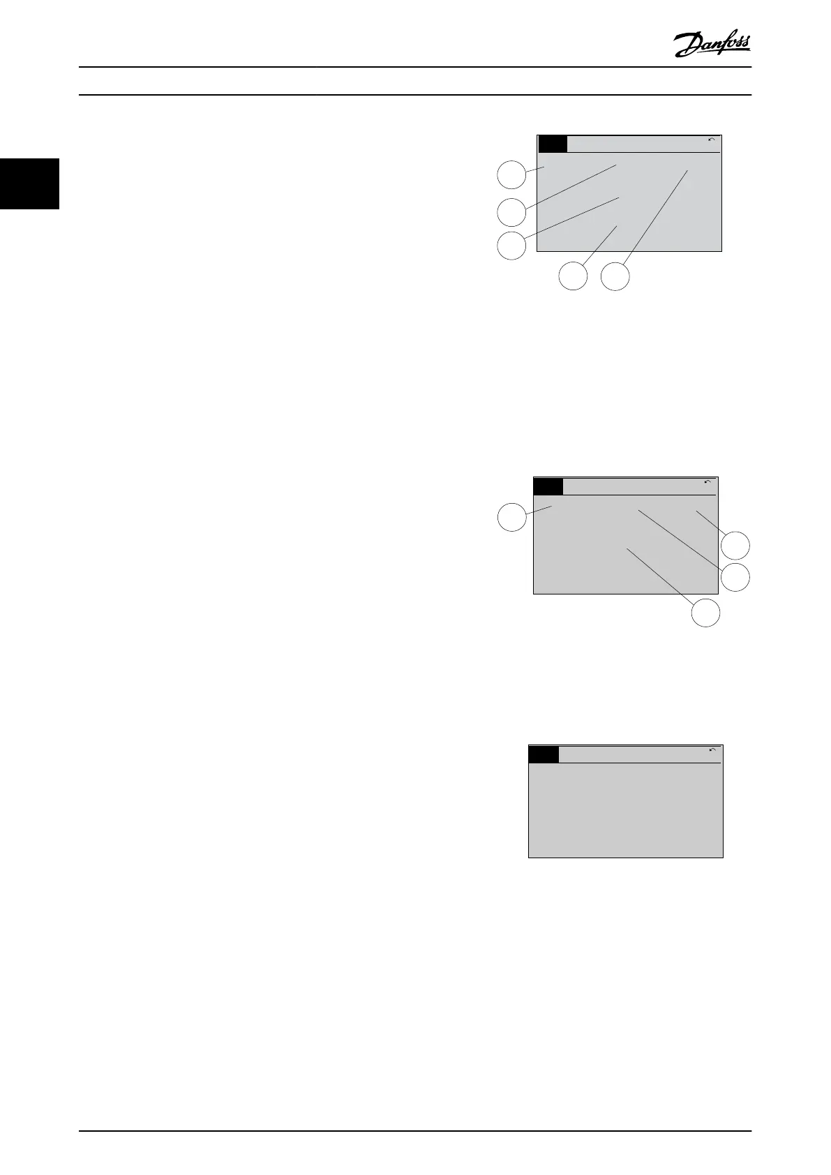
Status display I
This readout state is standard after start-up or initialization.
Press [INFO] to obtain information about the value/
measurement linked to the shown operating variables (1.1,
1.2, 1.3, 2, and 3).
See the operating variables shown in the display in
Illustration 2.2. 1.1, 1.2, and 1.3 are shown in small size. 2
and 3 are shown in medium size.
1.1
2
3
1.3
1.2
130BP041.10
799 RPM
Auto Remote Ramping
1 (1)
36.4 kw7.83 A
0.000
53.2 %
Status
Illustration 2.2 Example of Status Display I
Status display II
See the operating variables (1.1, 1.2, 1.3, and 2) shown in
the display in Illustration 2.3.
In the example, speed, motor current, motor power, and
frequency are selected as variables in the 1
st
and 2
nd
lines.
1.1, 1.2, and 1.3 are shown in small size. 2 is shown in
large size.
1.1
1.2
2
1.3
130BP062.10
207RPM
Auto Remote Running
1 (1)
24.4 kW5.25A
6.9
Hz
Status
Illustration 2.3 Example of Status Display II
Status display III
This state displays the event and action of the smart logic
control.
130BP063.10
778 RPM
Auto Remote Running
1 (1)
4.0 kW0.86 A
State: 0 o 0 (o)
When: -
Do: -
Status
Illustration 2.4 Example of Status Display III
How to Programme
VLT
®
HVAC Drive FC 102
12 Danfoss A/S © 10/2019 All rights reserved. M0010001
22
 Loading...


