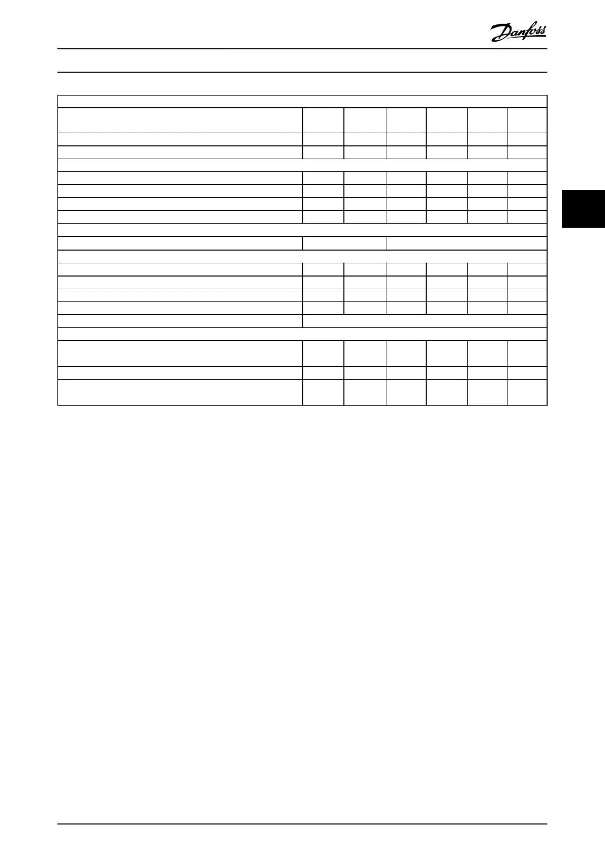
Sobrecarga normal del 150 % durante 1 minuto
Convertidor de frecuencia
Eje de salida típico [kW]
P5K5
5.5
P7K5
7.5
P11K
11
P15K
15
P18K
18.5
P22K
22
Eje de salida típico [CV] 7,5 10 15 20 25 30
Clasicación de protección de alojamiento IP20 M3 M3 M4 M4 M5 M5
Intensidad de salida
Continua (3 × 380-440 V) [A] 12,0 15,5 23,0 31,0 37,0 43,0
Intermitente (3 × 380-440 V) [A] 18,0 23,5 34,5 46,5 55,5 64,5
Continua (3 × 440-480 V) [A] 11,0 14,0 21,0 27,0 34,0 40,0
Intermitente (3 × 440-480 V) [A] 16,5 21,3 31,5 40,5 51,0 60,0
Dimensión máxima del cable:
(Alimentación, motor) [mm
2
/AWG]
4/10 16/6
Intensidad de entrada máxima
Continua (3 × 380-440 V) [A] 19,2 24,8 33,0 42,0 34,7 41,2
Intermitente (3 × 380-440 V) [A] 27,4 36,3 47,5 60,0 49,0 57,6
Continua (3 × 440-480 V) [A] 16,6 21,4 29,0 36,0 31,5 37,5
Intermitente (3 × 440-480 V) [A] 23,6 30,1 41,0 52,0 44,0 53,0
Fusibles de red máximos [A] Consulte chapter 1.3.3 Fuses.
Ambiente
Pérdida de potencia estimada [W]
más favorable/típica
1)
131.0/
166.8
175.0/
217.5
290.0/
342.0
387.0/
454.0
395.0/
428.0
467.0/
520.0
Peso protección IP20 [kg] 3,0 3,0
Rendimiento [%]
más favorable/típico
2)
98.0/
97.5
98.0/
97.5
97.8/
97.4
97.7/
97.4
98.1/
98.0
98.1/
97.9
Table 4.9 Fuente de alimentación de red 3 × 380-480 V CA
1) Se aplica para seleccionar las dimensiones de la refrigeración del convertidor de frecuencia. Si la frecuencia de conmutación es superior a los
ajustes predeterminados, las pérdidas de potencia pueden aumentar. Se incluyen los consumos de energía habituales del LCP y de la tarjeta de
control. Para conocer los datos de pérdida de potencia conforme a la norma EN 50598-2, consulte www.danfoss.com/vltenergyeciency.
2) Rendimiento medido en corriente nominal. Para conocer la clase de rendimiento energético, consulte el chapter 1.8.1 Surroundings. Para
conocer las pérdidas a carga parcial, consulte www.danfoss.com/vltenergyeciency.
Guía rápida
Quick Guide●Kurzanleitung●Guide rapide●Guía rápida●Guia Rápido●Краткое
руководство
MG02BB4P Danfoss A/S © 05/2016 All rights reserved. 103
4 4

 Loading...


