1.6 Troubleshooting
1.6.1 Warnings and Alarms
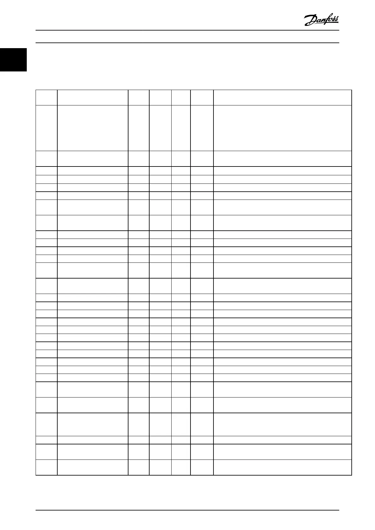
Number Description Warning Alarm Trip
Lock
Error Cause of problem
2 Live zero error X X Signal on terminal 53 or 60 is less than 50% of the value set
in:
•
parameter 6-10 Terminal 53 Low Voltage
•
parameter 6-12 Terminal 53 Low Current
•
parameter 6-22 Terminal 54 Low Current
4
Mains phase loss
1)
X X X Missing phase on supply side, or too high voltage imbalance.
Check supply voltage.
7
DC over voltage
1)
X X DC-link voltage exceeds the limit.
8
DC under voltage
1)
X X DC-link voltage drops below the voltage warning limit.
9 Inverter overloaded X X More than 100% load for too long.
10 Motor ETR overtemperature X X Motor is too hot. The load has exceeded 100% for too long.
11 Motor thermistor overtem-
perature
X X Thermistor or thermistor connection is disconnected.
12 Torque limit X Torque exceeds value set in either parameter 4-16 Torque Limit
Motor Mode or 4-17Torque Limit Generator Mode.
13 Overcurrent X X X Inverter peak current limit is exceeded.
14 Ground fault X X X Discharge from output phases to ground.
16 Short Circuit X X Short circuit in motor or on motor terminals.
17 Control word time-out X X No communication to frequency converter.
25 Brake resistor short-circuited X X Brake resistor is short-circuited, thus the brake function is
disconnected.
27 Brake chopper short-circuited X X Brake transistor is short-circuited, thus the brake function is
disconnected.
28 Brake check X Brake resistor is not connected/working.
29 Power board over temp X X X Heat sink cut-out temperature has been reached.
30 Motor phase U missing X X Motor phase U is missing. Check the phase.
31 Motor phase V missing X X Motor phase V is missing. Check the phase.
32 Motor phase W missing X X Motor phase W is missing. Check the phase.
38 Internal fault X X Contact local Danfoss supplier.
44 Ground fault X X Discharge from output phases to ground.
47 Control Voltage Fault X X 24 V DC is overloaded.
51 AMA check U
nom
and I
nom
X Wrong setting for motor voltage and/or motor current.
52 AMA low I
nom
X Motor current is too low. Check settings.
59 Current limit X Frequency converter overload.
63 Mechanical Brake Low X Actual motor current has not exceeded the release brake-
current within the start delay-time window.
80 Frequency Converter Initialised
to Default Value
X All parameter settings are initialised to default settings.
84 The connection between
frequency converter and LCP is
lost
X No communication between LCP and frequency converter.
85 Key disabled X See parameter group 0-4* LCP.
86 Copy fail X An error occurred while copying from frequency converter to
LCP, or from LCP to frequency converter.
87 LCP data invalid X Occurs when copying from LCP if the LCP contains erroneous
data - or if no data was uploaded to the LCP.
Quick Guide
VLT
®
Micro Drive FC 51
20 Danfoss A/S © 05/2016 All rights reserved. MG02BB4P
11

 Loading...


