EasyManuals Logo

Danfoss VLT Micro Drive FC 51 Quick Guide

Danfoss VLT Micro Drive FC 51
168 pages
To Next Page IconTo Next Page
To Previous Page IconTo Previous Page
Page #40 background imageLoading...
Page #40 background image
2.3.5 Elektrische Installation - Übersicht
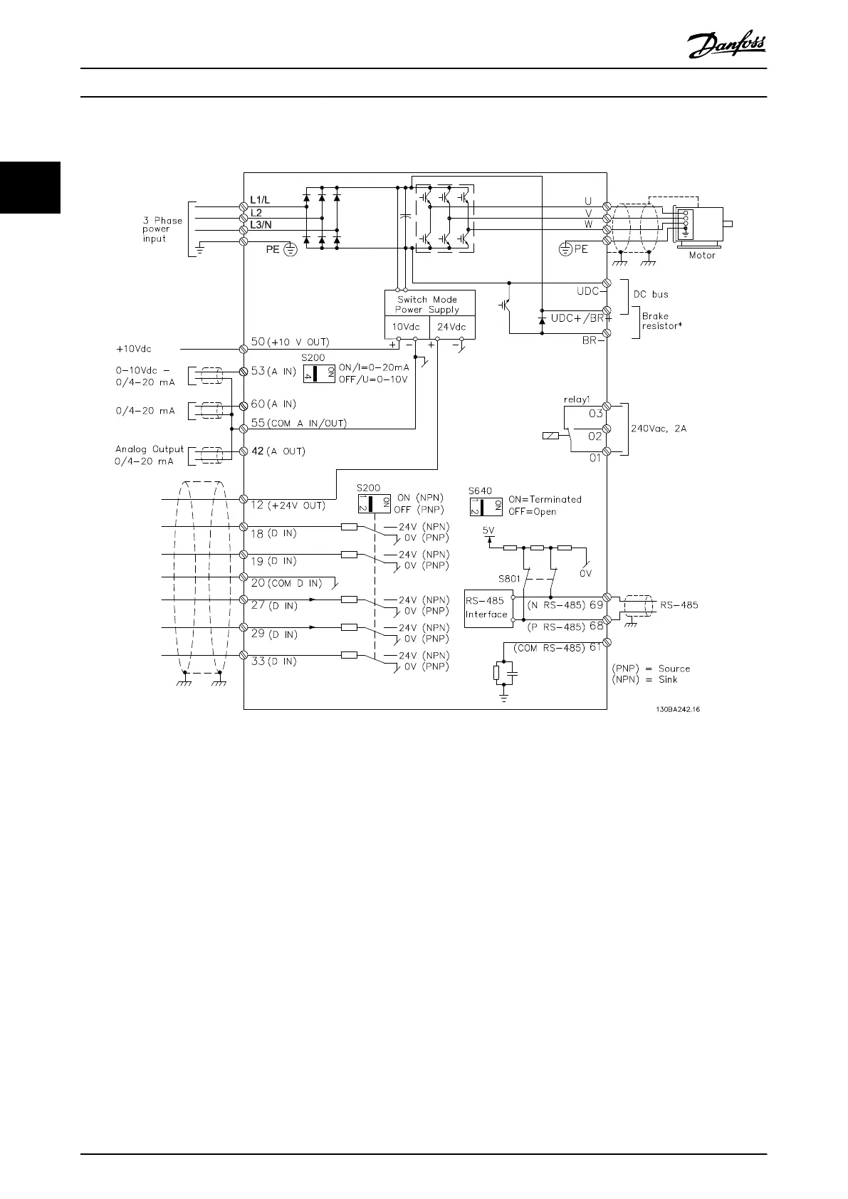
Illustration 2.6 Diagramm mit allen elektrischen Anschlüssen
* Bremsen (BR+ und BR-) für Baugröße M1 nicht zutreend.
Weitere Informationen zu Bremswiderständen nden Sie im Projektierungshandbuch VLT
®
Bremswiderstand MCE 101.
Eine Verbesserung des Leistungsfaktors und der EMV-Leistung ist durch Einbau optionaler Danfoss-Netzlter möglich.
Danfoss-Leistungslter können ebenfalls zur Zwischenkreiskopplung eingesetzt werden. Weitere Informationen zur
Zwischenkreiskopplung entnehmen Sie dem Anwendungshinweis VLT
®
FC 51 Micro Drive Zwischenkreiskopplung.
Kurzanleitung
VLT
®
Micro Drive FC 51
38 Danfoss A/S © 05/2016 All rights reserved. MG02BB4P
22

Table of Contents

Other manuals for Danfoss VLT Micro Drive FC 51

Questions and Answers:

Question and Answer IconNeed help?

Do you have a question about the Danfoss VLT Micro Drive FC 51 and is the answer not in the manual?

Danfoss VLT Micro Drive FC 51 Specifications

General IconGeneral
EnclosureIP20
Output Voltage0-100% of supply voltage
AltitudeUp to 1000 m without derating
Power Range0.18-22 kW
Control MethodV/f
CommunicationModbus RTU
Protection FeaturesOver-voltage, under-voltage, over-current, over-temperature
Ambient Temperature-10°C to 50°C
Storage Temperature-25°C to 65°C
Relative Humidity5-95% (non-condensing)
Input Voltage200-240 V, 380-480 V
Braking FunctionIntegrated braking chopper (optional)

Related product manuals