EasyManuals Logo

Danfoss VLT Micro Drive FC 51 Quick Guide

Danfoss VLT Micro Drive FC 51
168 pages
To Next Page IconTo Next Page
To Previous Page IconTo Previous Page
Page #15 background imageLoading...
Page #15 background image
1.3.5 Power Circuit - Overview
Illustration 1.6 Diagram Showing all Electrical Terminals
* Brakes (BR+ and BR-) are not applicable for enclosure size M1.
For information about brake resistors, see VLT
®
Brake Resistor MCE 101 Design Guide.
Improved power factor and EMC performance can be achieved by installing optional Danfoss line lters.
Danfoss power lters can also be used for load sharing. For more information about load sharing, see VLT
®
FC 51 Micro Drive
Load Sharing application note.
Quick Guide
Quick GuideKurzanleitungGuide rapideGuía rápidaGuia RápidoКраткое
руководство
MG02BB4P Danfoss A/S © 05/2016 All rights reserved. 13
1 1

Table of Contents

Other manuals for Danfoss VLT Micro Drive FC 51

Questions and Answers:

Question and Answer IconNeed help?

Do you have a question about the Danfoss VLT Micro Drive FC 51 and is the answer not in the manual?
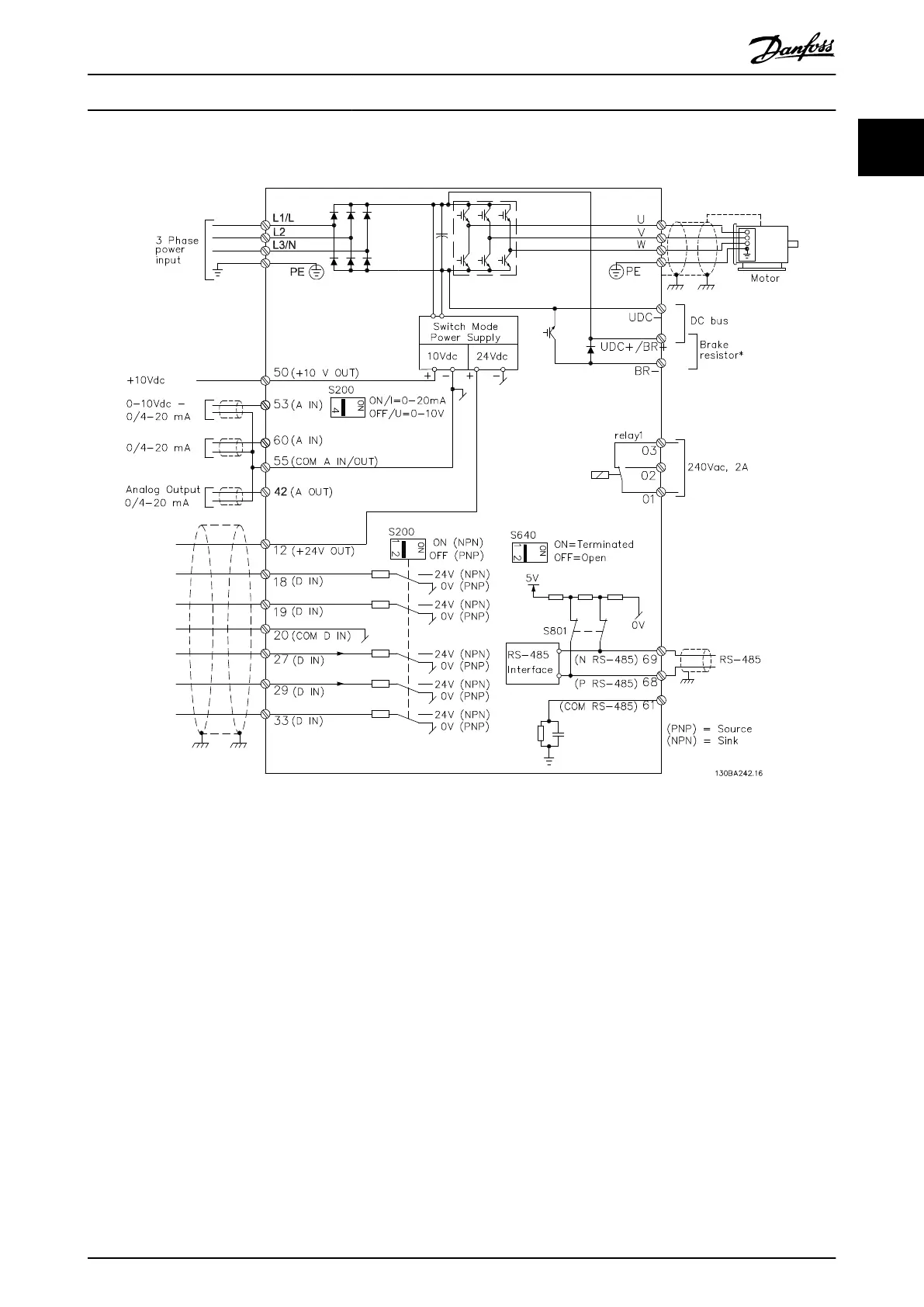
Danfoss VLT Micro Drive FC 51 Specifications

General IconGeneral
EnclosureIP20
Output Voltage0-100% of supply voltage
AltitudeUp to 1000 m without derating
Power Range0.18-22 kW
Control MethodV/f
CommunicationModbus RTU
Protection FeaturesOver-voltage, under-voltage, over-current, over-temperature
Ambient Temperature-10°C to 50°C
Storage Temperature-25°C to 65°C
Relative Humidity5-95% (non-condensing)
Input Voltage200-240 V, 380-480 V
Braking FunctionIntegrated braking chopper (optional)

Related product manuals