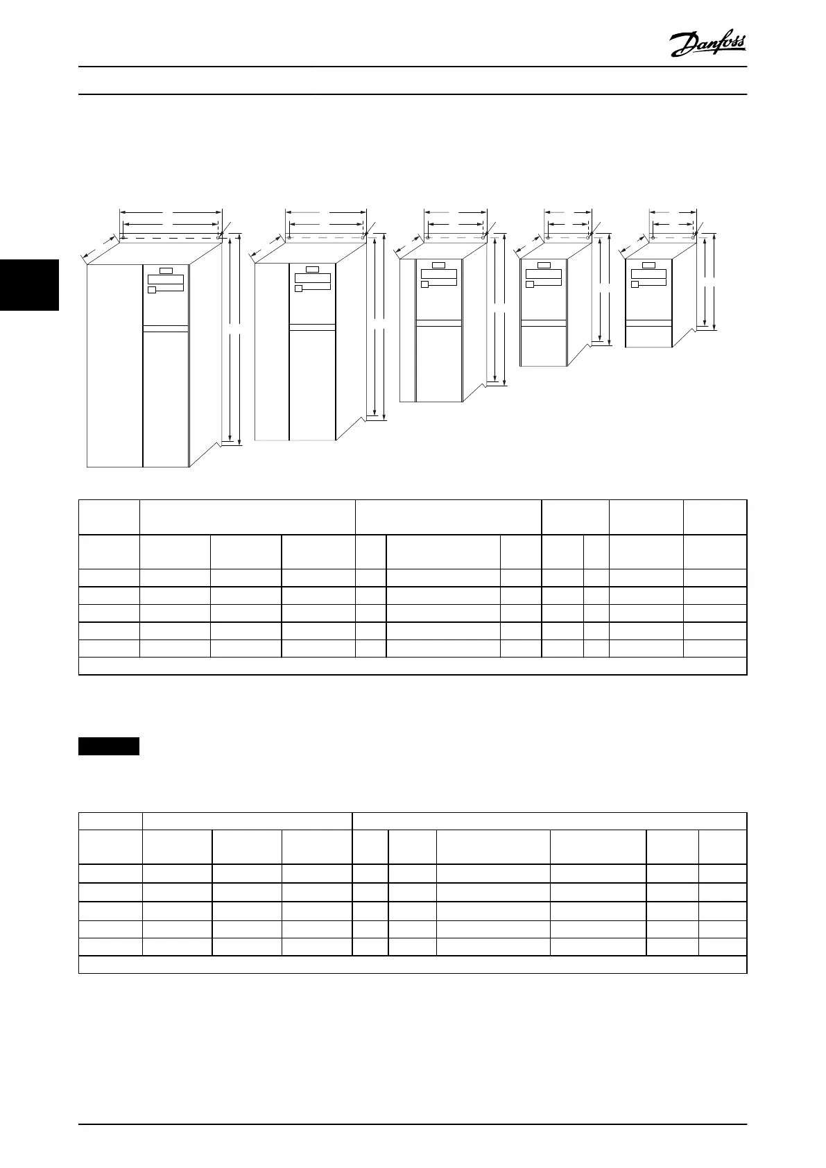
4.3.2 Dimensiones mecánicas
En la solapa del embalaje encontrará una plantilla para taladrar.
B
a A
a A
a A
a A
a A
C
C
C C C
b
B
b
B
b
B
b
B
b
Ø 7mm
M5
M4
M3
M2
M1
Ø 7mm Ø 5.5mm Ø 4.5mm
130BB321.11
Ø 4.5mm
Potencia [kW] Altura [mm] Anchura
[mm]
Profundidad
1)
[mm]
Peso
máximo
Protección
1 × 200-240
V
3 × 200-240
V
3 × 380-480
V
A
A (placa de desaco-
plamiento incluida)
a B b C [kg]
M1 0,18-0,75 0,25-0,75 0,37-0,75 150 205 140,4 70 55 148 1,1
M2 1,5 1,5 1,5-2,2 176 230 166,4 75 59 168 1,6
M3 2,2 2,2-3,7 3,0-7,5 239 294 226 90 69 194 3,0
M4 11,0-15,0 292 347,5 272,4 125 97 241 6,0
M5 18,5-22,0 335 387,5 315 165 140 248 9,5
1) Para LCP con potenciómetro, añadir 7,6 mm.
Illustration 4.1 Dimensiones mecánicas
NOTICE
Todos los cableados deben cumplir las normas locales y nacionales sobre las secciones transversales de cables y la
temperatura ambiente. Se recomienda usar conductores de cobre (de 60-75 °C).
Potencia [kW] Par [Nm]
Protección
1 × 200-240
V
3 × 200-240
V
3 × 380-480
V
Línea Motor Conexión CC/freno
Terminales de
control
Tierra Relé
M1 0,18-0,75 0,25-0,75 0,37-0,75 0,8 0,7
Horquilla
1)
0,15 3 0,5
M2 1,5 1,5 1,5-2,2 0,8 0,7
Horquilla
1)
0,15 3 0,5
M3 2,2 2,2-3,7 3,0-7,5 0,8 0,7
Horquilla
1)
0,15 3 0,5
M4 – – 11,0-15,0 1,3 1,3 1,3 0,15 3 0,5
M5 – – 18,5-22,0 1,3 1,3 1,3 0,15 3 0,5
1) Conectores de horquilla (terminales Faston de 6,3 mm [0,25 in])
Table 4.2 Apriete de los terminales
Guía rápida
VLT
®
Micro Drive FC 51
84 Danfoss A/S © 05/2016 All rights reserved. MG02BB4P
44

 Loading...


