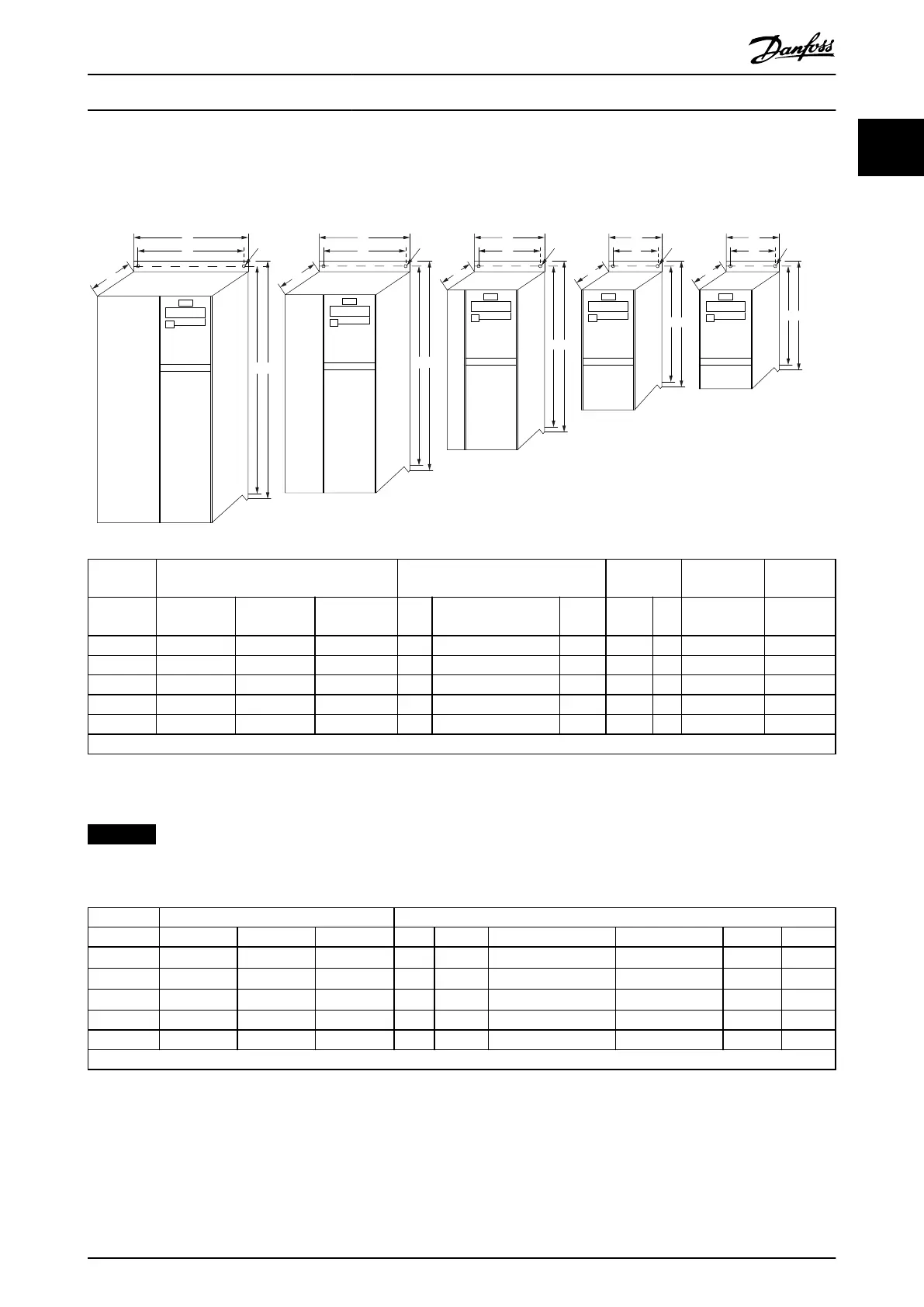
1.3.2 Mechanical Dimensions
A template for drilling is found on the ap of the packaging.
B
a A
a A
a A
a A
a A
C
C
C C C
b
B
b
B
b
B
b
B
b
Ø 7mm
M5
M4
M3
M2
M1
Ø 7mm Ø 5.5mm Ø 4.5mm
130BB321.11
Ø 4.5mm
Power [kW] Height [mm] Width [mm]
Depth
1)
[mm]
Maximum
weight
Enclosure 1x200-240 V 3x200-240 V 3x380-480 V A
A (including
decoupling plate)
a B b C [kg]
M1 0.18–0.75 0.25–0.75 0.37–0.75 150 205 140.4 70 55 148 1.1
M2 1.5 1.5 1.5–2.2 176 230 166.4 75 59 168 1.6
M3 2.2 2.2–3.7 3.0–7.5 239 294 226 90 69 194 3.0
M4 11.0–15.0 292 347.5 272.4 125 97 241 6.0
M5 18.5–22.0 335 387.5 315 165 140 248 9.5
1) For LCP with potentiometer, add 7.6 mm.
Illustration 1.1 Mechanical Dimensions
NOTICE
All cabling must comply with national and local regulations on cable cross-sections and ambient temperature. Copper
conductors required, (60–75 °C) recommended.
Power [kW] Torque [Nm]
Enclosure 1x200–240 V 3x200–240 V 3x380–480 V Line Motor DC connection/brake Control terminals Ground Relay
M1 0.18–0.75 0.25–0.75 0.37–0.75 0.8 0.7
Spade
1)
0.15 3 0.5
M2 1.5 1.5 1.5–2.2 0.8 0.7
Spade
1)
0.15 3 0.5
M3 2.2 2.2–3.7 3.0–7.5 0.8 0.7
Spade
1)
0.15 3 0.5
M4 – – 11.0–15.0 1.3 1.3 1.3 0.15 3 0.5
M5 – – 18.5–22.0 1.3 1.3 1.3 0.15 3 0.5
1) Spade connectors (6.3 mm (0.25 in) Faston plugs)
Table 1.2 Tightening of Terminals
Quick Guide
Quick Guide●Kurzanleitung●Guide rapide●Guía rápida●Guia Rápido●Краткое
руководство
MG02BB4P Danfoss A/S © 05/2016 All rights reserved. 9
1 1

 Loading...


