EasyManuals Logo

Danfoss VLT Micro Drive FC 51 Quick Guide

Danfoss VLT Micro Drive FC 51
168 pages
To Next Page IconTo Next Page
To Previous Page IconTo Previous Page
Page #90 background imageLoading...
Page #90 background image
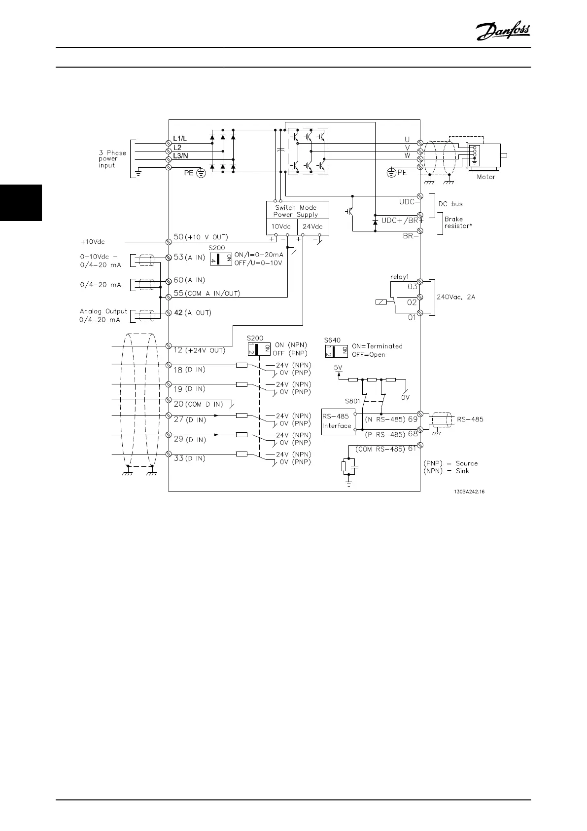
4.3.5 Circuito de potencia - Presentación
Illustration 4.6 Diagrama que muestra todos los terminales eléctricos
* Los frenos (BR+ y BR–) no son aplicables para el alojamiento de tamaño M1.
Para obtener más información sobre las resistencias de frenado, consulte la Guía de diseño de la VLT
®
Brake Resistor MCE 101.
Se puede mejorar el factor de potencia y el rendimiento de CEM instalando los ltros de línea opcionales de Danfoss.
También pueden utilizarse los ltros de potencia de Danfoss para carga compartida. Para obtener más información sobre
carga compartida, consulte la Nota sobre la aplicación de la carga compartida del VLT
®
FC 51 Micro Drive.
Guía rápida
VLT
®
Micro Drive FC 51
88 Danfoss A/S © 05/2016 All rights reserved. MG02BB4P
44

Table of Contents

Other manuals for Danfoss VLT Micro Drive FC 51

Questions and Answers:

Question and Answer IconNeed help?

Do you have a question about the Danfoss VLT Micro Drive FC 51 and is the answer not in the manual?

Danfoss VLT Micro Drive FC 51 Specifications

General IconGeneral
EnclosureIP20
Output Voltage0-100% of supply voltage
AltitudeUp to 1000 m without derating
Power Range0.18-22 kW
Control MethodV/f
CommunicationModbus RTU
Protection FeaturesOver-voltage, under-voltage, over-current, over-temperature
Ambient Temperature-10°C to 50°C
Storage Temperature-25°C to 65°C
Relative Humidity5-95% (non-condensing)
Input Voltage200-240 V, 380-480 V
Braking FunctionIntegrated braking chopper (optional)

Related product manuals