1.7 Specications
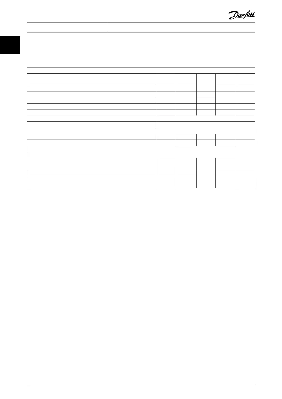
1.7.1 Mains Supply 1x200–240 V AC
Normal overload 150% for 1 minute
Frequency converter
Typical shaft output [kW]
PK18
0.18
PK37
0.37
PK75
0.75
P1K5
1.5
P2K2
2.2
Typical shaft output [hp] 0.25 0.5 1 2 3
Enclosure protection rating IP20 M1 M1 M1 M2 M3
Output current
Continuous (1x200–240 V AC) [A] 1.2 2.2 4.2 6.8 9.6
Intermittent (1x200–240 V AC) [A] 1.8 3.3 6.3 10.2 14.4
Maximum cable size:
(Mains, motor) [mm
2
/AWG]
4/10
Maximum input current
Continuous (1x200–240 V) [A] 3.3 6.1 11.6 18.7 26.4
Intermittent (1x200–240 V) [A] 4.5 8.3 15.6 26.4 37.0
Maximum mains fuses [A] See chapter 1.3.3 Fuses
Environment
Estimated power loss [W],
Best case/typical
1)
12.5/
15.5
20.0/
25.0
36.5/
44.0
61.0/
67.0
81.0/
85.1
Weight enclosure IP20 [kg] 1.1 1.1 1.1 1.6 3.0
Eciency [%],
Best case/typical
2)
95.6/
94.5
96.5/
95.6
96.6/
96.0
97.0/
96.7
96.9/
97.1
Table 1.6 Mains Supply 1x200–240 V AC
1) Applies for dimensioning of frequency converter cooling. If the switching frequency is higher than the default setting, the power losses may
increase. LCP and typical control card power consumptions are included. For power loss data according to EN 50598-2, refer to
www.danfoss.com/
vltenergyeciency.
2) Eciency measured at nominal current. For energy eciency class, see chapter 1.8.1 Surroundings. For part load losses, see www.danfoss.com/
vltenergyeciency.
Quick Guide
VLT
®
Micro Drive FC 51
22 Danfoss A/S © 05/2016 All rights reserved. MG02BB4P
11

 Loading...


