1.3.3 Connecting to Mains and Motor
The frequency converter is designed to operate all
standard 3-phased asynchronous motors.
The frequency converter is designed to accept mains/
motor cables with a maximum cross-section of 4 mm
2
/10
AWG (M1, M2 and M3), and a maximum cross-section of 16
mm
2
/6 AWG (M4 and M5).
•
Use a shielded/armoured motor cable to comply
with EMC emission specications, and connect
this cable to both the decoupling plate and the
motor metal.
•
Keep motor cable as short as possible to reduce
the noise level and leakage currents.
•
For further details on mounting of the decoupling
plate, see VLT
®
Micro Drive FC 51 Decoupling
Mounting Plate Instructions.
•
Also see the chapter EMC-correct Electrical Instal-
lation in the VLT
®
Micro Drive FC 51 Design Guide.
1. Mount the ground wires to PE terminal.
2. Connect motor to terminals U, V, and W.
3. Mount mains supply to terminals L1/L, L2, and
L3/N (3-phase) or L1/L and L3/N (single-phase)
and tighten.
Illustration 1.2 Mounting of Ground Cable, Mains, and Motor
Wires
1.3.4 Control Terminals
All control cable terminals are located underneath the
terminal cover in front of the frequency converter. Remove
the terminal cover using a screwdriver.
NOTICE
See the back of the terminal cover for outlines of control
terminals and switches.
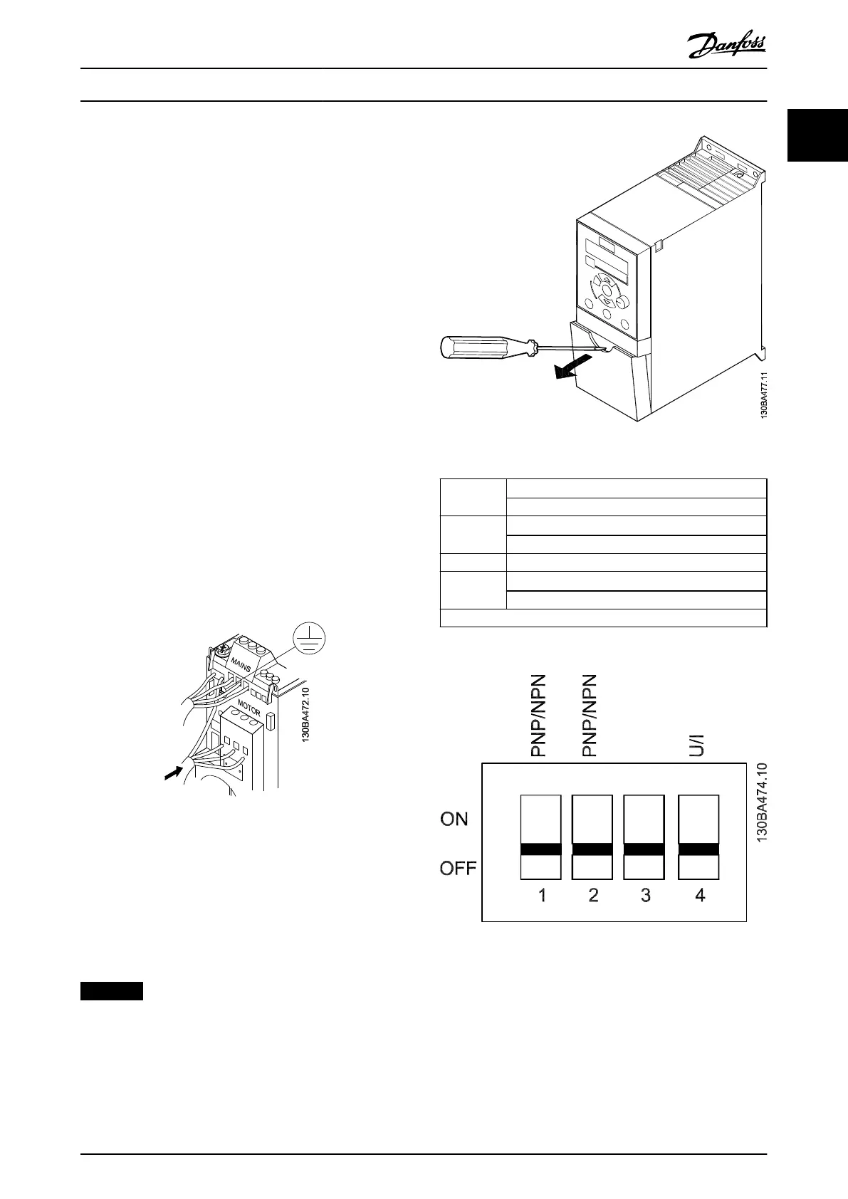
Do not operate switches with power on the frequency
converter.
Set 6-19 Terminal 53 Mode according to Switch 4
position.
Illustration 1.3 Removing Terminal Cover
Switch 1
O=PNP terminals 29
1)
On=NPN terminals 29
Switch 2
O=PNP terminal 18, 19, 27 and 33
1)
On=NPN terminal 18, 19, 27 and 33
Switch 3 No function
Switch 4
O=Terminal 53 0–10 V
1)
On=Terminal 53 0/4-20 mA
1)=default setting
Table 1.4 Settings for S200 Switches 1–4
Illustration 1.4 S200 Switches 1–4
Illustration 1.5 shows all control terminals of the frequency
converter. Applying Start (terminal 18) and an analog
reference (terminal 53 or 60) make the frequency converter
run.
Quick Guide
Quick Guide●Kurzanleitung●Guide rapide●Guía rápida●Guia Rápido●Краткое
руководство
MG02BB4P Danfoss A/S © 05/2016 All rights reserved. 11
1 1

 Loading...


