Surcharge normale (150 %) pendant 1 minute
Variateur de fréquence
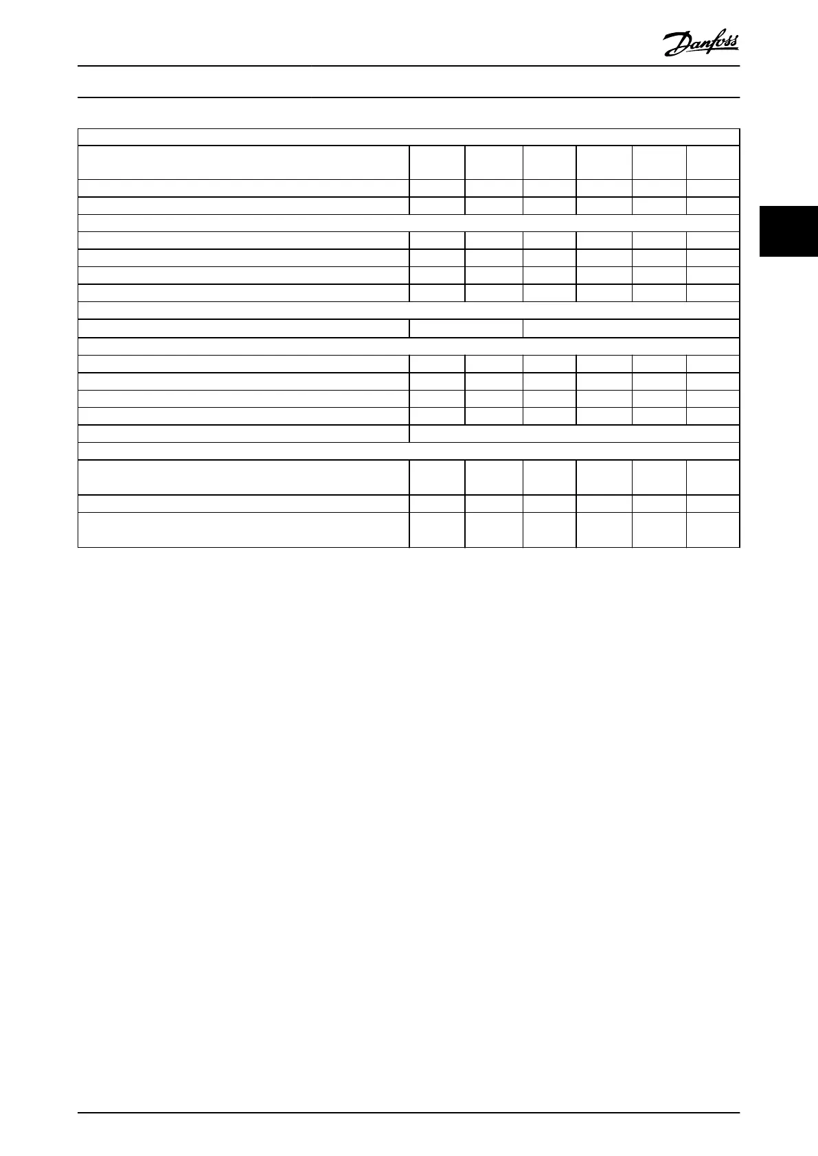
Sortie d'arbre typique [kW]
P5K5
5.5
P7K5
7.5
P11K
11
P15K
15
P18K
18.5
P22K
22
Sortie d'arbre typique [HP] 7,5 10 15 20 25 30
Protection nominale IP20 M3 M3 M4 M4 M5 M5
Courant de sortie
Continu (3 x 380-440 V) [A] 12,0 15,5 23,0 31,0 37,0 43,0
Intermittent (3 x 380-440 V) [A] 18,0 23,5 34,5 46,5 55,5 64,5
Continu (3 x 440-480 V) [A] 11,0 14,0 21,0 27,0 34,0 40,0
Intermittent (3 x 440-480 V) [A] 16,5 21,3 31,5 40,5 51,0 60,0
Section du câble maximale :
(secteur, moteur) [mm
2
/AWG]
4/10 16/6
Courant d'entrée maximal
Continu (3 x 380-440 V) [A] 19,2 24,8 33,0 42,0 34,7 41,2
Intermittent (3 x 380-440 V) [A] 27,4 36,3 47,5 60,0 49,0 57,6
Continu (3 x 440-480 V) [A] 16,6 21,4 29,0 36,0 31,5 37,5
Intermittent (3 x 440-480 V) [A] 23,6 30,1 41,0 52,0 44,0 53,0
Fusibles secteur maximum [A] Voir le chapter 1.3.3 Fuses
Environnement
Perte de puissance estimée [W]
Meilleur cas/typique
1)
131.0/
166.8
175.0/
217.5
290.0/
342.0
387.0/
454.0
395.0/
428.0
467.0/
520.0
Poids du boîtier IP20 [kg] 3,0 3,0
Rendement [%]
Meilleur cas/typique
2)
98.0/
97.5
98.0/
97.5
97.8/
97.4
97.7/
97.4
98.1/
98.0
98.1/
97.9
Table 3.9 Alimentation secteur 3 x 380-480 V CA
1) S'applique au dimensionnement du refroidissement de variateur de fréquence. Si la fréquence de commutation est supérieure au réglage par
défaut, les pertes de puissance peuvent augmenter. Les puissances consommées par le LCP et la carte de commande sont incluses. Pour les
données des pertes de puissance selon la norme EN 50598-2, consulter www.danfoss.com/vltenergyeciency.
2) Rendement mesuré au courant nominal. Pour la classe d'ecacité énergétique, voir le chapter 1.8.1 Surroundings.. Pour les pertes de charge
partielles, voir www.danfoss.com/vltenergyeciency.
Guide rapide
Quick Guide●Kurzanleitung●Guide rapide●Guía rápida●Guia Rápido●Краткое
руководство
MG02BB4P Danfoss A/S © 05/2016 All rights reserved. 75
3 3

 Loading...


