DS8100
12
2
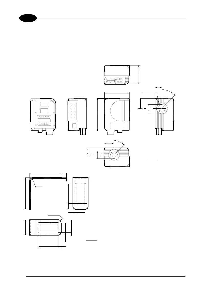
2.3 MECHANICAL INSTALLATION
DS8100 can be installed to operate in any position.
There are 16 screw holes (M6 X 8) on the sides of the scanner for mounting.
The diagram below gives all the information required for installation; refer to par. 2.5 for
correct positioning of the scanner with respect to the code passage zone.
126.5
4.98
46.7
1.83
M6 N°16
67.5
2.65
50
1.96
45°
170.5
6.71
215.5
8.48
45°
67.5
2.65
46.7
1.83
1.96
50
mm
inch
164
6.45
R 15
0.59
5
0.19
164
6.45
100
3.93
30
1.18
16
0.63
48
1.88
R 15 N°4
0.59
80
3.15
100
3.93
15
0.59
17.5
0.68
45
1.77
8.5 N° 4
0.33
mm
inch
Figure 9 - DS8100 overall dimensions
MOUNTING BRACKET
 Loading...