INSTALLATION – DS8100 SERIAL INTERFACE
23
2
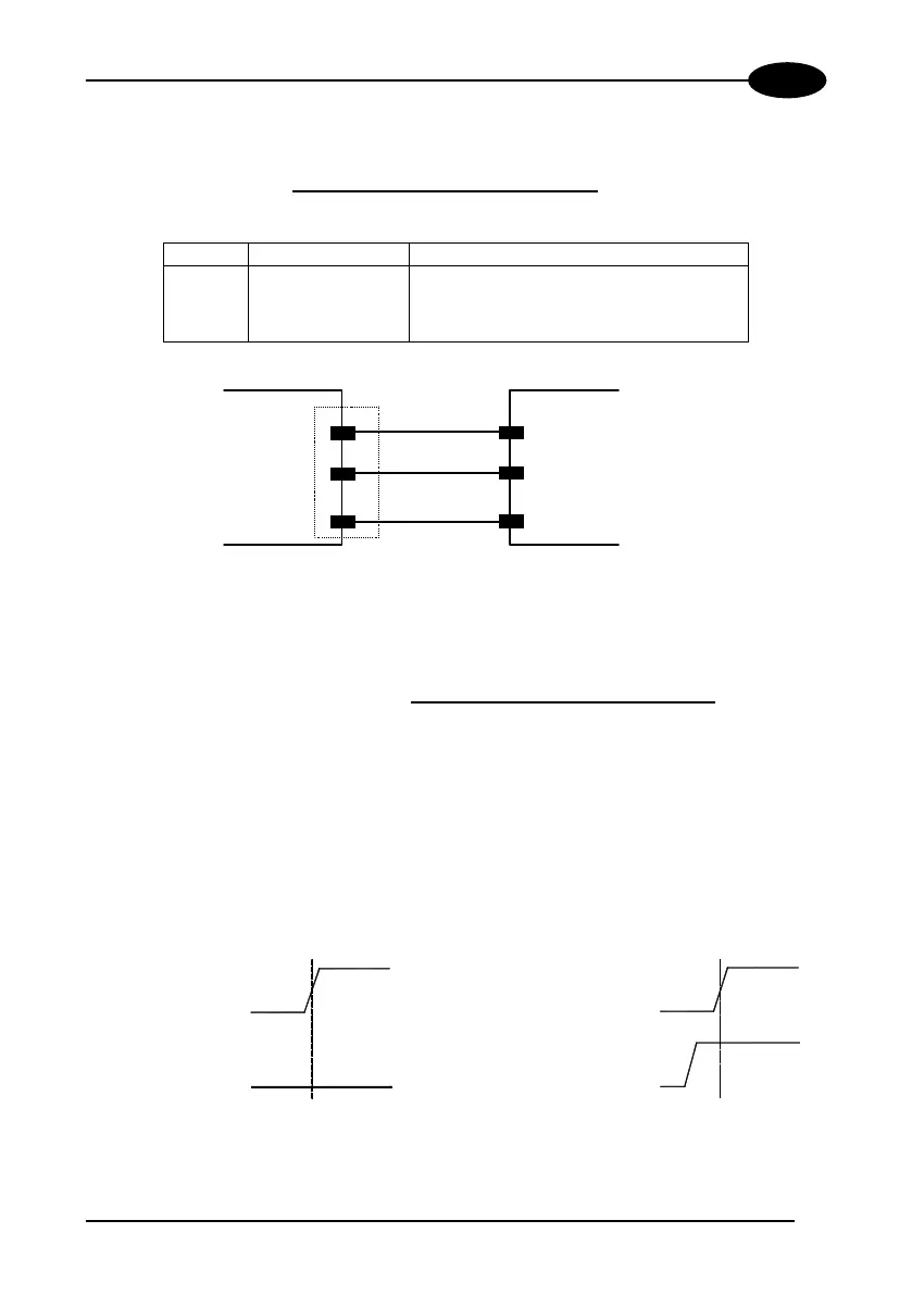
RS485 Half-Duplex Auxiliary Interface
The following pins of the Aux. Interface A and B connectors (Figure A, 13 and 14) are
used:
Pin Name Function
1 GND485 Ground
8 RTX485+ transmit/receive data +
9 RTX485- transmit/receive data -
DS8100
USER INTERFACE
RTX485+
RTX485-
9
RTX485-
RTX485+
8
1
GND485
GND485
Figure 21 - RS485 Auxiliary interface connections
2.4.5 Inputs
The inputs of the scanner are on the Input Signal A and B connectors on the body
of the DS8100 (Figure A, 13 and 14).
These inputs are called ENC/PS3, PS1 and PS2.
ENC is the Encoder input. In PackTrack™ operating mode, it detects the conveyor
speed.
When PackTrack™ operating mode is not used, this is the PS3 input which can be
used to control the oscillating mirror reading positions. See the following figure.
PS1
PS3
INACTIVE
ACTIVE
INACTIVE
SETPOINT 1
POSITION 2
PS3
PS1
INACTIVE
INACTIVE
ACTIVE
ACTIVE
POSITION 1
SETPOINT 2
Figure 22 - PS3 control signal
 Loading...