INSTALLATION – DS8100 BUS INTERFACE
39
3
The Tilt angle is represented by the value T in Figure 45. For code reconstruction, see
par. 4.1.1.
Figure 45 – "Tilt" angle
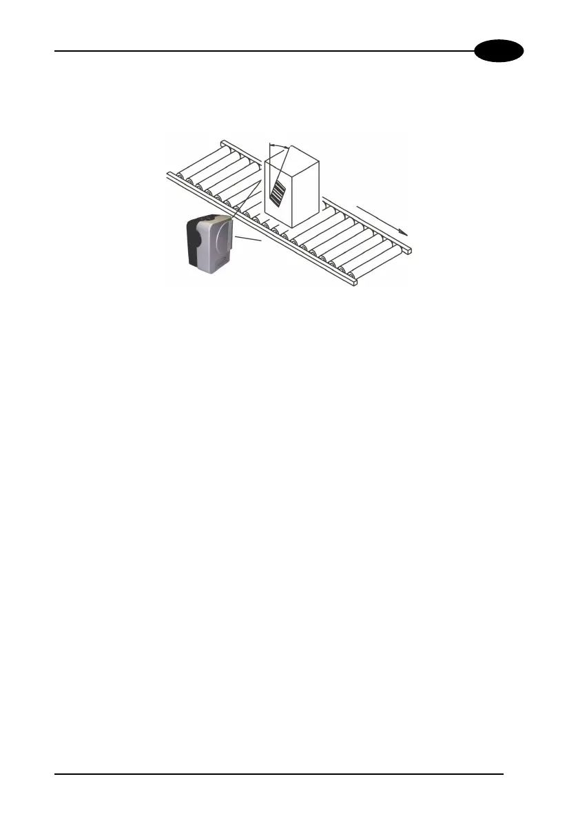
3.5 TYPICAL LAYOUT
The scanner is generally activated by a photoelectric sensor used as a code
presence sensor when the object enters its reading zone.
The following figures show a typical layout for DS8100 Bus Interface.
A Lonworks cable provides a communication line (branch) between up to 4 scanners
and an SC8000 unit. The last scanner on the line requires a Termination connector.
Up to 4 branches of this type can be connected to a single SC8000. The allowed
maximum length of the cable is 65 m.
External devices such as a presence sensor, an encoder and the supply unit are all
connected to the SC8000, which collects all signals driving them to all scanners.
The SC8000 is also connected to a Host.
T
 Loading...