INSTALLATION – DS8100 BUS INTERFACE
35
3
3.3 ELECTRICAL CONNECTIONS
The DS8100 Bus Interface version employs a Lonworks network used for both input
and output connections to build a multi-sided or omni-station system connecting
several DS8100 scanners and one or more SC8000 units.
This version is equipped with the following 3 connectors:
• Lonworks INPUT male connector (17 pins) (Figure B, 12).
• Lonworks OUTPUT female connector (17 pins) (Figure B, 13).
• RS232 debug connector – for Service only, (9 pins) (Figure B, 14).
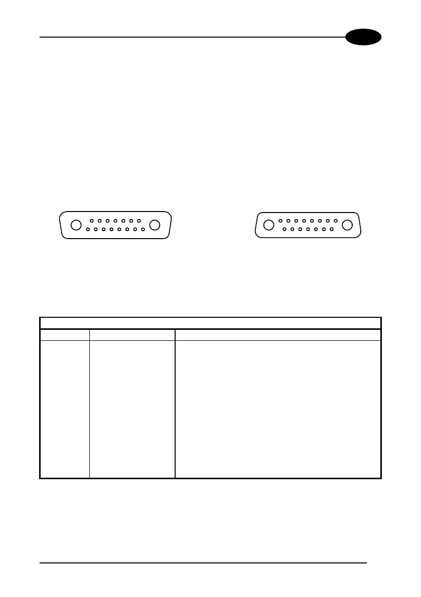
Lonworks Input/Output Connector
A1
A2
1
15
scanner side
external view
A1
A2
1
15
OUTPUT
INPUT
Figure 40 - Lonworks INPUT/OUTPUT connectors
The following pinout is valid for the INPUT connector as well as for the OUTPUT
connector.
Lonworks INPUT/OUTPUT Connector pinout
Pin Name Function
A1 GND supply voltage (negative pin)
A2 VS supply voltage 20 to 30 vdc (positive pin)
1 Shield A
3 Shield B
8 Lon A+ lonworks a line (positive pin)
9 Lon A- lonworks a line (negative pin)
10 Lon B+ lonworks b line (positive pin)
11 Lon B- lonworks b line (negative pin)
12 PS+ presence sensor
13 ENC+ encoder input
14 PSAux+ auxiliary presence sensor
15 Refer- input reference
 Loading...