INSTALLATION – DS8100 SERIAL INTERFACE
21
2
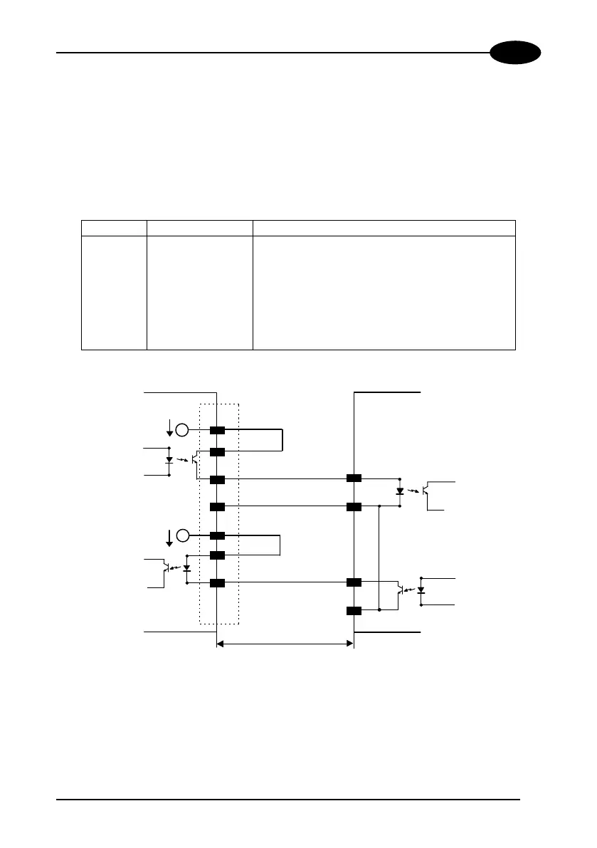
20 mA Current Loop Interface
The DS8100 has two current generators (one for transmission and one for reception),
allowing for both active and passive type connections.
The following pins of the Main Interface connector (Figure A, 15) are used for 20 mA
C.L. connections:
Pin Name Function
1 DRVREF current generator reference
2 CLOUT+ current loop output +
3 CLOUT- current loop output -
4 DRVIN input current generator
7 CLIN+ current loop input +
8 CLIN- current loop input -
9 DRVOUT output current generator
DS8100
USER INTERFACE
MAX. 300 METERS
C.L. IN-
C.L. IN+
C.L. OUT-
C.L. OUT+
DRVREF
DRVIN
8
7
3
2
1
4
9
DRVOUT
I = 20 mA
I = 20 mA
Figure 18 - 20 mA C.L. active connections
 Loading...