INSTALLATION – DS8100 SERIAL INTERFACE
25
2
Signal
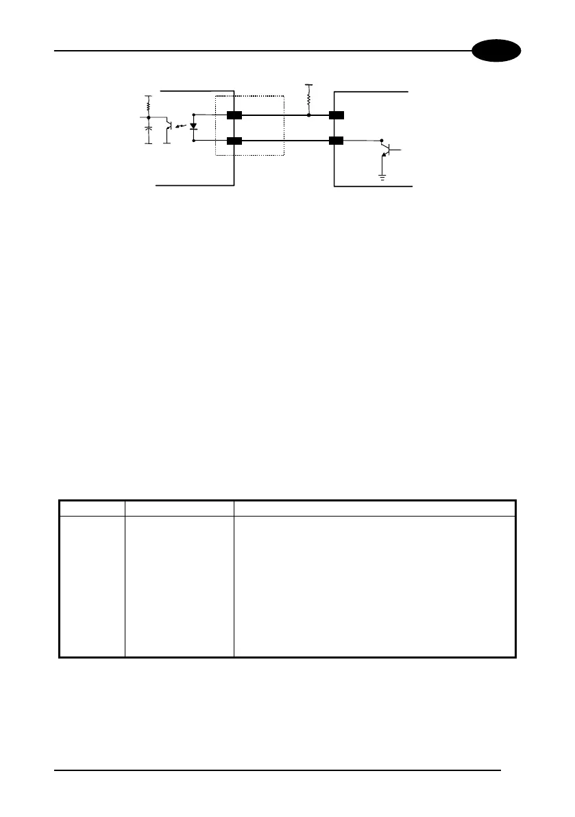
INPUT DEVICE
+
-
10/12/14
11/13/15
+
DS8100
V
Vext
Figure 26 - NPN input command using external power
Isolation between the command logic and the scanner is maintained by powering the
inputs with a different supply voltage (Vext) from that supplied on the Aux.
Interface/Input Signal A and B connectors (VS).
The driving logic of the input signals may be powered, for convenience, with the
voltage supply between pins A2 (VS) and A1 (GND) of the connector. In this case,
however, the device is no longer electrically isolated.
The electrical features of these inputs are:
Maximum voltage 30 V
Maximum current 25 mA
2.4.6 Outputs
The relative signals are available on the Output Signal connector (Figure A, 16).
Pin Name Function
1 VS power for external devices (Positive pin)
2 GND power for external devices (Negative pin)
3 NO READ+ no read output +
4 NO READ- no read output -
5 RIGHT+ right code output +
6 RIGHT- right code output -
7
8
SPS+
SPS-
slave presence sensor +
slave presence sensor -
9 N.C. not connected
A D.C. output voltage, the same as that powering the DS8100, is present between pins
1 and 2. This may be used to power external devices: electrical isolation between the
scanner and external devices is lost in this case.
 Loading...