INSTALLATION – DS8100 SERIAL INTERFACE
13
2
2.4 ELECTRICAL CONNECTIONS
2.4.1 DS8100 Connectors
The DS8100 Serial Interface version is equipped with 4 connectors for the following
signals:
Aux. Interface/Input Signal connector A (male, 17 pins) (Figure A, 13).
Aux. Interface/Input Signal connector B (female, 17 pins) (Figure A, 14).
Output Signal connector (female, 9 pins) (Figure A, 16).
Main Interface connector (female, 9 pins) (Figure A, 15).
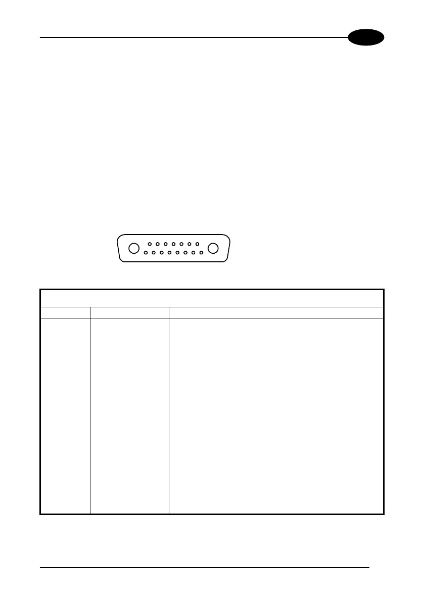
Aux. Interface/Input Signal Connector A
A1
A2
1
15
scanner side
external view
Figure 10 - Aux. Interface/Input Signal connector A (male)
Aux. Interface/Input Signal Connector A pinout
Pin Name Function
A1 GND ground
A2 VS power supply
1 GND485 RS485 ground reference
2 NC not connected
3 NC not connected
4 NC not connected
5 NC not connected
6 NC not connected
7 NC not connected
8 RXTX485+ positive transmit/receive
9 RXTX485- negative transmit/receive
10 ENC+/PS3+ encoder/presence sensor 3 signal (positive pin)
11 ENC-/PS3- encoder/presence sensor 3 signal (negative pin)
12 PS2+ presence sensor 2 signal (positive pin)
13 PS2- presence sensor 2 signal (negative pin)
14 PS1+ presence sensor 1 signal (positive pin)
15 PS1- presence sensor 1 signal (negative pin)
 Loading...